
How does ideCAD define design response spectrum, according to ASCE 7-16?
-
By using the parameters determined in Table 12.2-1 and 11.5.1, the Reduced Design Spectral acceleration, Sa is determined automatically according to Section 12.9.1.2.
-
According to the structural system type, using the R, Cd and Ωo coefficients obtained from Table 12.2-1, R/Ie and the reduced design spectral acceleration are calculated automatically.
Symbols
Cd = Deflection amplification factor
Ie= Seismic importance factor
R = Response modification coefficient
The reduced design spectral acceleration Sa, which is the ordinate of the reduced design acceleration spectrum for a given natural vibration period T, used to determine the reduced seismic loads in the horizontal direction, is that of Sa Design Response Spectrum., is obtained by dividing the R, Reduced Design Response Spectrum for Modal Analysis per ASCE 7-16 §12.9.1.2 and multiply with Ie.
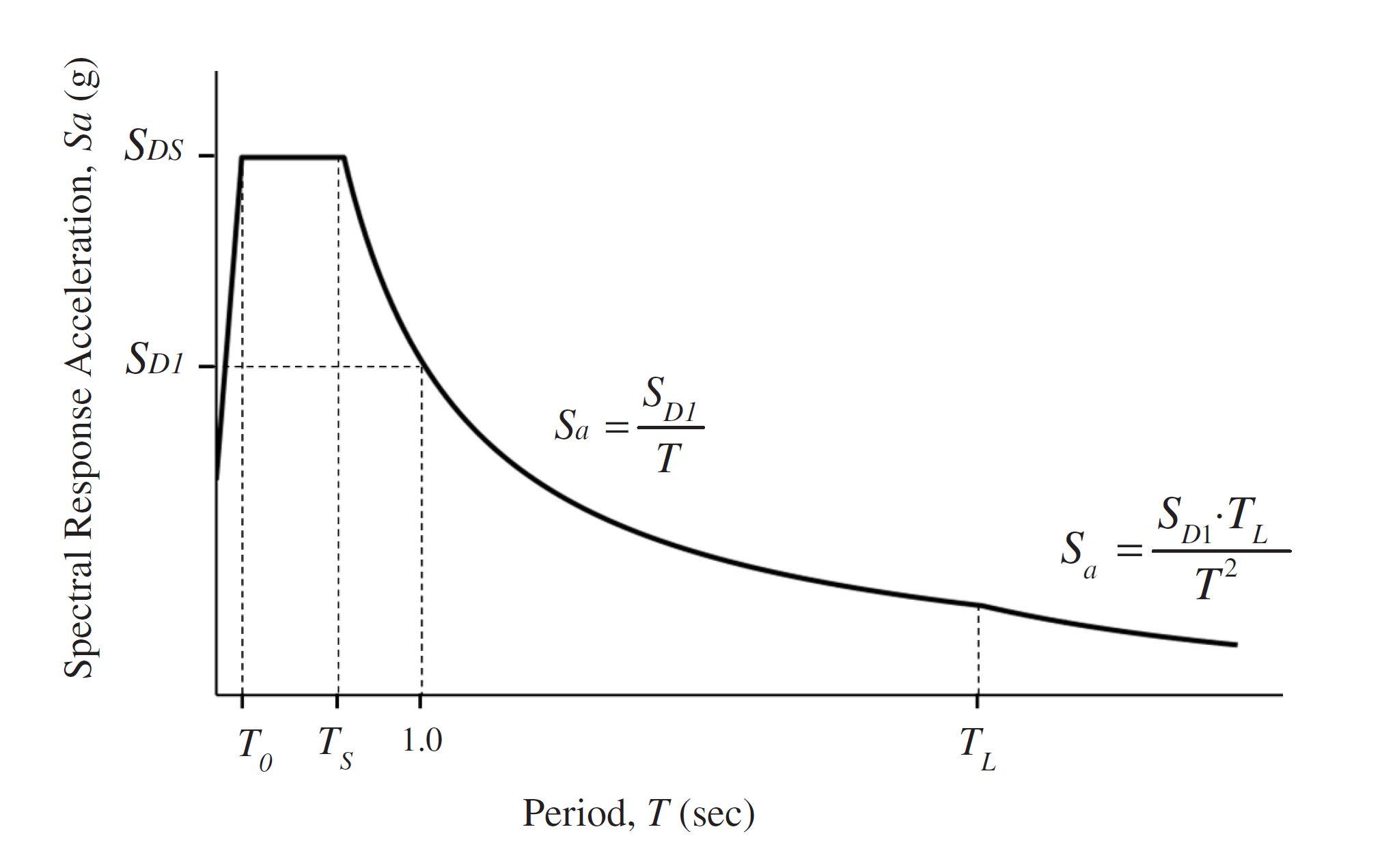
On the Analysis ASCE 7-16 Wizard - Design Spectra tab, the spectral acceleration coefficients obtained from USGB based on the coordinates and the horizontal elastic design spectrum Sa is calculated according to the formula below. Design Response Spectrum. is represented by a total of 4 functions, different in each region, and shown in the function below.
-
It’s determined with the equation 11.4-5 from T=0 to T0 .
'%3e%3cg transform='translate(167%2c0)'%3e%3cg transform='translate(-13%2c0)'%3e%3cuse xlink:href='%23MJMATHI-53' x='0' y='0'%3e%3c/use%3e%3cuse transform='scale(0.707)' xlink:href='%23MJMATHI-61' x='867' y='-213'%3e%3c/use%3e%3cuse xlink:href='%23MJMAIN-3D' x='1365' y='0'%3e%3c/use%3e%3cg transform='translate(2421%2c0)'%3e%3cuse xlink:href='%23MJMATHI-53' x='0' y='0'%3e%3c/use%3e%3cg transform='translate(613%2c-155)'%3e%3cuse transform='scale(0.707)' xlink:href='%23MJMATHI-44' x='0' y='0'%3e%3c/use%3e%3cuse transform='scale(0.707)' xlink:href='%23MJMATHI-53' x='828' y='0'%3e%3c/use%3e%3c/g%3e%3c/g%3e%3cuse xlink:href='%23MJSZ3-28' x='4177' y='-1'%3e%3c/use%3e%3cg transform='translate(4914%2c0)'%3e%3cuse xlink:href='%23MJMAIN-30'%3e%3c/use%3e%3cuse xlink:href='%23MJMAIN-2E' x='500' y='0'%3e%3c/use%3e%3cuse xlink:href='%23MJMAIN-34' x='779' y='0'%3e%3c/use%3e%3c/g%3e%3cuse xlink:href='%23MJMAIN-2B' x='6415' y='0'%3e%3c/use%3e%3cg transform='translate(7416%2c0)'%3e%3cuse xlink:href='%23MJMAIN-30'%3e%3c/use%3e%3cuse xlink:href='%23MJMAIN-2E' x='500' y='0'%3e%3c/use%3e%3cuse xlink:href='%23MJMAIN-36' x='779' y='0'%3e%3c/use%3e%3c/g%3e%3cg transform='translate(8696%2c0)'%3e%3cg transform='translate(120%2c0)'%3e%3crect stroke='none' width='846' height='60' x='0' y='220'%3e%3c/rect%3e%3cuse transform='scale(0.707)' xlink:href='%23MJMATHI-54' x='246' y='602'%3e%3c/use%3e%3cg transform='translate(60%2c-405)'%3e%3cuse transform='scale(0.707)' xlink:href='%23MJMATHI-54' x='0' y='0'%3e%3c/use%3e%3cuse transform='scale(0.5)' xlink:href='%23MJMATHI-6F' x='826' y='-213'%3e%3c/use%3e%3c/g%3e%3c/g%3e%3c/g%3e%3cuse xlink:href='%23MJSZ3-29' x='9782' y='-1'%3e%3c/use%3e%3c/g%3e%3cg transform='translate(17507%2c0)'%3e%3cuse xlink:href='%23MJMAIN-28' x='0' y='0'%3e%3c/use%3e%3cg transform='translate(389%2c0)'%3e%3cuse xlink:href='%23MJMAIN-31'%3e%3c/use%3e%3cuse xlink:href='%23MJMAIN-31' x='500' y='0'%3e%3c/use%3e%3cuse xlink:href='%23MJMAIN-2E' x='1001' y='0'%3e%3c/use%3e%3cuse xlink:href='%23MJMAIN-34' x='1279' y='0'%3e%3c/use%3e%3c/g%3e%3cuse xlink:href='%23MJMAIN-2212' x='2391' y='0'%3e%3c/use%3e%3cuse xlink:href='%23MJMAIN-35' x='3392' y='0'%3e%3c/use%3e%3cuse xlink:href='%23MJMAIN-29' x='3892' y='0'%3e%3c/use%3e%3c/g%3e%3c/g%3e%3c/g%3e%3c/svg%3e)
-
It’s equal SDS from T0 to Ts .
-
It’s determined with the equation 11.4-6 from Ts to TL .
'%3e%3cg transform='translate(167%2c0)'%3e%3cg transform='translate(-13%2c0)'%3e%3cg transform='translate(0%2c-63)'%3e%3cuse xlink:href='%23MJMATHI-53' x='0' y='0'%3e%3c/use%3e%3cuse transform='scale(0.707)' xlink:href='%23MJMATHI-61' x='867' y='-213'%3e%3c/use%3e%3cuse xlink:href='%23MJMAIN-3D' x='1365' y='0'%3e%3c/use%3e%3cg transform='translate(2144%2c0)'%3e%3cg transform='translate(397%2c0)'%3e%3crect stroke='none' width='1289' height='60' x='0' y='220'%3e%3c/rect%3e%3cg transform='translate(60%2c531)'%3e%3cuse transform='scale(0.707)' xlink:href='%23MJMATHI-53' x='0' y='0'%3e%3c/use%3e%3cg transform='translate(433%2c-107)'%3e%3cuse transform='scale(0.5)' xlink:href='%23MJMATHI-44' x='0' y='0'%3e%3c/use%3e%3cuse transform='scale(0.5)' xlink:href='%23MJMAIN-31' x='828' y='0'%3e%3c/use%3e%3c/g%3e%3c/g%3e%3cuse transform='scale(0.707)' xlink:href='%23MJMATHI-54' x='559' y='-573'%3e%3c/use%3e%3c/g%3e%3c/g%3e%3c/g%3e%3c/g%3e%3cg transform='translate(10938%2c0)'%3e%3cg transform='translate(0%2c-63)'%3e%3cuse xlink:href='%23MJMAIN-28' x='0' y='0'%3e%3c/use%3e%3cg transform='translate(389%2c0)'%3e%3cuse xlink:href='%23MJMAIN-31'%3e%3c/use%3e%3cuse xlink:href='%23MJMAIN-31' x='500' y='0'%3e%3c/use%3e%3cuse xlink:href='%23MJMAIN-2E' x='1001' y='0'%3e%3c/use%3e%3cuse xlink:href='%23MJMAIN-34' x='1279' y='0'%3e%3c/use%3e%3c/g%3e%3cuse xlink:href='%23MJMAIN-2212' x='2391' y='0'%3e%3c/use%3e%3cuse xlink:href='%23MJMAIN-36' x='3392' y='0'%3e%3c/use%3e%3cuse xlink:href='%23MJMAIN-29' x='3892' y='0'%3e%3c/use%3e%3c/g%3e%3c/g%3e%3c/g%3e%3c/g%3e%3c/svg%3e)
-
It’s determined with the equation 11.4-7 for periods greater than TL.
'%3e%3cg transform='translate(167%2c0)'%3e%3cg transform='translate(-13%2c0)'%3e%3cg transform='translate(0%2c6)'%3e%3cuse xlink:href='%23MJMATHI-53' x='0' y='0'%3e%3c/use%3e%3cuse transform='scale(0.707)' xlink:href='%23MJMATHI-61' x='867' y='-213'%3e%3c/use%3e%3cuse xlink:href='%23MJMAIN-3D' x='1365' y='0'%3e%3c/use%3e%3cg transform='translate(2144%2c0)'%3e%3cg transform='translate(397%2c0)'%3e%3crect stroke='none' width='2113' height='60' x='0' y='220'%3e%3c/rect%3e%3cg transform='translate(60%2c532)'%3e%3cuse transform='scale(0.707)' xlink:href='%23MJMATHI-53' x='0' y='0'%3e%3c/use%3e%3cg transform='translate(433%2c-107)'%3e%3cuse transform='scale(0.5)' xlink:href='%23MJMATHI-44' x='0' y='0'%3e%3c/use%3e%3cuse transform='scale(0.5)' xlink:href='%23MJMAIN-31' x='828' y='0'%3e%3c/use%3e%3c/g%3e%3cg transform='translate(1169%2c0)'%3e%3cuse transform='scale(0.707)' xlink:href='%23MJMATHI-54' x='0' y='0'%3e%3c/use%3e%3cuse transform='scale(0.5)' xlink:href='%23MJMATHI-4C' x='826' y='-213'%3e%3c/use%3e%3c/g%3e%3c/g%3e%3cg transform='translate(634%2c-546)'%3e%3cuse transform='scale(0.707)' xlink:href='%23MJMATHI-54' x='0' y='0'%3e%3c/use%3e%3cuse transform='scale(0.5)' xlink:href='%23MJMAIN-32' x='1047' y='572'%3e%3c/use%3e%3c/g%3e%3c/g%3e%3c/g%3e%3c/g%3e%3c/g%3e%3cg transform='translate(11763%2c0)'%3e%3cg transform='translate(0%2c6)'%3e%3cuse xlink:href='%23MJMAIN-28' x='0' y='0'%3e%3c/use%3e%3cg transform='translate(389%2c0)'%3e%3cuse xlink:href='%23MJMAIN-31'%3e%3c/use%3e%3cuse xlink:href='%23MJMAIN-31' x='500' y='0'%3e%3c/use%3e%3cuse xlink:href='%23MJMAIN-2E' x='1001' y='0'%3e%3c/use%3e%3cuse xlink:href='%23MJMAIN-34' x='1279' y='0'%3e%3c/use%3e%3c/g%3e%3cuse xlink:href='%23MJMAIN-2212' x='2391' y='0'%3e%3c/use%3e%3cuse xlink:href='%23MJMAIN-37' x='3392' y='0'%3e%3c/use%3e%3cuse xlink:href='%23MJMAIN-29' x='3892' y='0'%3e%3c/use%3e%3c/g%3e%3c/g%3e%3c/g%3e%3c/g%3e%3c/svg%3e)
'%3e%3cg transform='translate(167%2c0)'%3e%3cg transform='translate(-13%2c0)'%3e%3cg transform='translate(0%2c1404)'%3e%3cuse xlink:href='%23MJMATHI-54' x='0' y='0'%3e%3c/use%3e%3cuse transform='scale(0.707)' xlink:href='%23MJMAIN-30' x='826' y='-213'%3e%3c/use%3e%3cuse xlink:href='%23MJMAIN-3D' x='1316' y='0'%3e%3c/use%3e%3cg transform='translate(2372%2c0)'%3e%3cuse xlink:href='%23MJMAIN-30'%3e%3c/use%3e%3cuse xlink:href='%23MJMAIN-2E' x='500' y='0'%3e%3c/use%3e%3cuse xlink:href='%23MJMAIN-32' x='779' y='0'%3e%3c/use%3e%3c/g%3e%3cuse xlink:href='%23MJMAIN-28' x='3651' y='0'%3e%3c/use%3e%3cg transform='translate(4041%2c0)'%3e%3cuse xlink:href='%23MJMATHI-53' x='0' y='0'%3e%3c/use%3e%3cg transform='translate(613%2c-150)'%3e%3cuse transform='scale(0.707)' xlink:href='%23MJMATHI-44' x='0' y='0'%3e%3c/use%3e%3cuse transform='scale(0.707)' xlink:href='%23MJMAIN-31' x='828' y='0'%3e%3c/use%3e%3c/g%3e%3c/g%3e%3cuse xlink:href='%23MJMAIN-2F' x='5694' y='0'%3e%3c/use%3e%3cg transform='translate(6195%2c0)'%3e%3cuse xlink:href='%23MJMATHI-53' x='0' y='0'%3e%3c/use%3e%3cg transform='translate(613%2c-155)'%3e%3cuse transform='scale(0.707)' xlink:href='%23MJMATHI-44' x='0' y='0'%3e%3c/use%3e%3cuse transform='scale(0.707)' xlink:href='%23MJMATHI-53' x='828' y='0'%3e%3c/use%3e%3c/g%3e%3c/g%3e%3cuse xlink:href='%23MJMAIN-29' x='7950' y='0'%3e%3c/use%3e%3c/g%3e%3cg transform='translate(0%2c-47)'%3e%3cuse xlink:href='%23MJMATHI-54' x='0' y='0'%3e%3c/use%3e%3cuse transform='scale(0.707)' xlink:href='%23MJMATHI-53' x='826' y='-219'%3e%3c/use%3e%3cuse xlink:href='%23MJMAIN-3D' x='1418' y='0'%3e%3c/use%3e%3cg transform='translate(2474%2c0)'%3e%3cuse xlink:href='%23MJMATHI-53' x='0' y='0'%3e%3c/use%3e%3cg transform='translate(613%2c-150)'%3e%3cuse transform='scale(0.707)' xlink:href='%23MJMATHI-44' x='0' y='0'%3e%3c/use%3e%3cuse transform='scale(0.707)' xlink:href='%23MJMAIN-31' x='828' y='0'%3e%3c/use%3e%3c/g%3e%3c/g%3e%3cuse xlink:href='%23MJMAIN-2F' x='4128' y='0'%3e%3c/use%3e%3cg transform='translate(4628%2c0)'%3e%3cuse xlink:href='%23MJMATHI-53' x='0' y='0'%3e%3c/use%3e%3cg transform='translate(613%2c-155)'%3e%3cuse transform='scale(0.707)' xlink:href='%23MJMATHI-44' x='0' y='0'%3e%3c/use%3e%3cuse transform='scale(0.707)' xlink:href='%23MJMATHI-53' x='828' y='0'%3e%3c/use%3e%3c/g%3e%3c/g%3e%3c/g%3e%3cg transform='translate(0%2c-1498)'%3e%3cuse xlink:href='%23MJMATHI-54' x='0' y='0'%3e%3c/use%3e%3cuse transform='scale(0.707)' xlink:href='%23MJMATHI-4C' x='826' y='-213'%3e%3c/use%3e%3cuse xlink:href='%23MJMAIN-3D' x='1444' y='0'%3e%3c/use%3e%3cuse xlink:href='%23MJMATHI-6C' x='2500' y='0'%3e%3c/use%3e%3cuse xlink:href='%23MJMATHI-6F' x='2798' y='0'%3e%3c/use%3e%3cuse xlink:href='%23MJMATHI-6E' x='3284' y='0'%3e%3c/use%3e%3cuse xlink:href='%23MJMATHI-67' x='3884' y='0'%3e%3c/use%3e%3cuse xlink:href='%23MJMAIN-2212' x='4587' y='0'%3e%3c/use%3e%3cuse xlink:href='%23MJMATHI-70' x='5588' y='0'%3e%3c/use%3e%3cuse xlink:href='%23MJMATHI-65' x='6091' y='0'%3e%3c/use%3e%3cuse xlink:href='%23MJMATHI-72' x='6558' y='0'%3e%3c/use%3e%3cuse xlink:href='%23MJMATHI-69' x='7009' y='0'%3e%3c/use%3e%3cuse xlink:href='%23MJMATHI-6F' x='7355' y='0'%3e%3c/use%3e%3cuse xlink:href='%23MJMATHI-64' x='7840' y='0'%3e%3c/use%3e%3cuse xlink:href='%23MJMATHI-74' x='8642' y='0'%3e%3c/use%3e%3cuse xlink:href='%23MJMATHI-72' x='9003' y='0'%3e%3c/use%3e%3cuse xlink:href='%23MJMATHI-61' x='9455' y='0'%3e%3c/use%3e%3cuse xlink:href='%23MJMATHI-6E' x='9984' y='0'%3e%3c/use%3e%3cuse xlink:href='%23MJMATHI-73' x='10585' y='0'%3e%3c/use%3e%3cuse xlink:href='%23MJMATHI-69' x='11054' y='0'%3e%3c/use%3e%3cuse xlink:href='%23MJMATHI-74' x='11400' y='0'%3e%3c/use%3e%3cuse xlink:href='%23MJMATHI-69' x='11761' y='0'%3e%3c/use%3e%3cuse xlink:href='%23MJMATHI-6F' x='12107' y='0'%3e%3c/use%3e%3cuse xlink:href='%23MJMATHI-6E' x='12592' y='0'%3e%3c/use%3e%3cuse xlink:href='%23MJMATHI-70' x='13470' y='0'%3e%3c/use%3e%3cuse xlink:href='%23MJMATHI-65' x='13974' y='0'%3e%3c/use%3e%3cuse xlink:href='%23MJMATHI-72' x='14440' y='0'%3e%3c/use%3e%3cuse xlink:href='%23MJMATHI-69' x='14892' y='0'%3e%3c/use%3e%3cuse xlink:href='%23MJMATHI-6F' x='15237' y='0'%3e%3c/use%3e%3cuse xlink:href='%23MJMATHI-64' x='15723' y='0'%3e%3c/use%3e%3c/g%3e%3c/g%3e%3c/g%3e%3c/g%3e%3c/svg%3e)
In the Analysis Settings - Response Spectrum Function tab, the horizontal design spectrum is determined and shown using the design spectral response acceleration parameters.
|
Structural System Type |
Response Modification Coefficient, R |
Overstrengh Factor, Ωo |
Deflection Amplification Factor, Cd |
Structural System Limitations Including Structural Height, hn (ft) Limits |
||||
|---|---|---|---|---|---|---|---|---|
|
Seismic Design Category |
||||||||
|
B |
C |
D |
E |
F |
||||
|
A. Bearing Wall Systems |
||||||||
|
A1 - Special reinforced concrete shear walls |
5 |
21/2 |
5 |
NL |
NL |
160 |
160 |
100 |
|
A2 - Ordinary reinforced concrete shear walls |
4 |
21/2 |
4 |
NL |
NL |
NP |
NP |
NP |
|
A3 - Detailed plain concrete shear walls |
2 |
21/2 |
2 |
NL |
NP |
NP |
NP |
NP |
|
A4 - Ordinary plain concrete shear walls |
11/2 |
21/2 |
11/2 |
NL |
NP |
NP |
NP |
NP |
|
B. Building Frame Systems |
||||||||
|
B1 - Steel eccentrically braced frames |
8 |
2 |
4 |
NL |
NL |
160 |
160 |
100 |
|
B2 - Steel special concentrically braced frames |
6 |
2 |
5 |
NL |
NL |
160 |
160 |
100 |
|
B3 - Steel ordinary concentrically braced frames |
31/4 |
2 |
31/4 |
NL |
NL |
35 |
35 |
NP |
|
B4 - Special reinforced concrete shear walls |
6 |
21/2 |
5 |
NL |
NL |
160 |
160 |
100 |
|
B5 - Ordinary reinforced concrete shear walls |
5 |
21/2 |
41/2 |
NL |
NL |
NP |
NP |
NP |
|
B6 - Detailed plain concrete shear walls |
2 |
21/2 |
2 |
NL |
NP |
NP |
NP |
NP |
|
B7 - Ordinary plain concrete shear walls |
11/2 |
21/2 |
11/2 |
NL |
NP |
NP |
NP |
NP |
|
C. Moment-Resisting Frame Systems |
||||||||
|
C1 - Steel special moment frames |
8 |
3 |
51/2 |
NL |
NL |
NL |
NL |
NL |
|
C2 - Steel special truss moment frames |
7 |
3 |
51/2 |
NL |
NL |
160 |
100 |
NP |
|
C3 - Steel intermediate moment frames |
41/2 |
3 |
4 |
NL |
NL |
35 |
NP |
NP |
|
C4 - Steel ordinary moment frames |
31/2 |
3 |
3 |
NL |
NL |
NP |
NP |
NP |
|
C5 - Special reinforced concrete moment frames |
8 |
3 |
51/2 |
NL |
NL |
NL |
NL |
NL |
|
C6 - Intermediate reinforced concrete moment frames |
5 |
3 |
41/2 |
NL |
NL |
NP |
NP |
NP |
|
C7 - Ordinary reinforced concrete moment frames |
3 |
3 |
21/2 |
NL |
NP |
NP |
NP |
NP |
|
D. Dual Systems with Special Moment Frames Capable of Resisting at Least 25% of Prescribed Seismic Foces |
||||||||
|
D1 - Steel eccentrically braced frames |
8 |
21/2 |
4 |
NL |
NL |
NL |
NL |
NL |
|
D2 - Steel special concentrically braced frames |
7 |
21/2 |
51/2 |
NL |
NL |
NL |
NL |
NL |
|
D3 - Special reinforced concrete shear walls |
7 |
21/2 |
51/2 |
NL |
NL |
NL |
NL |
NL |
|
D4 - Ordinary reinforced concrete shear walls |
6 |
21/2 |
5 |
NL |
NL |
NP |
NP |
NP |
|
E. Dual Systems with Intermediate Moment Frames Capable of Resisting at Least 25% of Prescribed Seismic Foces |
||||||||
|
E1 - Steel special concentrically braced frames |
6 |
21/2 |
5 |
NL |
NL |
35 |
NP |
NP |
|
E2 - Special reinforced concrete shear walls |
61/2 |
21/2 |
5 |
NL |
NL |
160 |
100 |
100 |
|
E8 - Ordinary reinforced concrete shear walls |
51/2 |
21/2 |
41/2 |
NL |
NL |
NP |
NP |
NP |
|
F. Shear Wall-Frame Interactive System with Ordinary Reinforced Concrete Moment Frames And Ordinary Reinforced Concrete Shear Walls |
||||||||
|
F1 - Shear wall-frame interactive system |
41/2 |
21/2 |
4 |
NL |
NP |
NP |
NP |
NP |
|
G. Cantilevered Column Systems Detailed to Conform to the Requirement for |
||||||||
|
G1 - Steel special cantilever column systems |
21/2 |
11/4 |
21/2 |
35 |
35 |
35 |
35 |
35 |
|
G2 - Steel ordinary cantilever column systems |
11/4 |
11/4 |
11/4 |
35 |
35 |
NP |
NP |
NP |
|
G3 - Special reinforced concrete moment frames |
21/2 |
11/4 |
21/2 |
35 |
35 |
35 |
35 |
35 |
|
G4 - Intermediate reinforced concrete moment frames |
11/2 |
11/4 |
11/2 |
35 |
35 |
NP |
NP |
NP |
|
G5 - Ordinary reinforced concrete moment frames |
1 |
11/4 |
1 |
35 |
NP |
NP |
NP |
NP |
|
H. Steel Systems not Specifically Detailed for Seismic Resistance, Excluding Cantilever Column Systems |
||||||||
|
H - Steel Systems not Specifically Detailed for Seismic Resistance |
3 |
3 |
3 |
NL |
NL |
NP |
NP |
NP |