
How does ideCAD design composite beams with steel-headed studs according to AISC 360-16?
-
Composite beams with steel-headed stud design is made automatically per AISC 360-16.
-
The user can change composite slab design settings and secondary steel beam settings.
Steel composite beams with steel-headed stud flexural design according to AISC 360-16 are explained in detail under this title.
Symbols
Asa = Cross-sectional Area of steel headed stud anchor, in.2 (mm2)
Ec = Modulus of elasticity of Asa = cross-sectional Area of steel headed stud anchor, in.2 (mm2)
Fu = Specified minimum tensile strength of a steel headed stud anchor, ksi (MPa)
As = Area of steel cross-section, in.2 (mm2)
d3 = distance from the resultant steel tension force for full section tension yield to the top of the steel, in.
ILB = Lower bound Moment of inertia, in.4 (mm4)
Is = Moment of inertia for the structural steel section, in.4 (mm4)
ΣQn = Sum of the nominal strengths of steel anchors between the point of the maximum positive Moment and the point of zero Moment to either side, kips (kN)
Ac = Area of the concrete slab within effective width, in.2 (mm2)
Fy = Specified minimum yield stress of steel, ksi (MPa)
fc′ =Specified compressive strength of concrete, ksi (MPa)
d1 = distance from the centroid of the compression force, C, in the concrete to the top of the steel section, in. (mm)
d2 = distance from the centroid of the compression force in the steel section to the top of the steel section, in. (mm). For the case of no compression in the steel section, d2 = 0.
Py = Tensile strength of the steel section;
Flexural Moment Strength
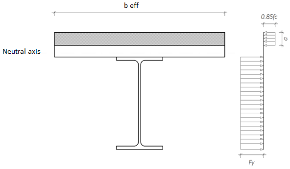
Concrete Slab Effective Width, beff
According to AISC 360-16 I3.1a, the effective width of the concrete slab is determined by the Sum of the effective widths for each side of the beam centerline, each of which does not exceed:
-
one-eighth of the beam span, center-to-center of supports;
-
one-half the distance to the centerline of the adjacent beam
-
The distance to the edge of the slab
Positive Flexural Strength
-
The design flexural strength =
-
The allowable flexural strength =
Plastic Stress Distrubution
The nominal plastic moment strength of the composite beam, Mn, is determined according to AISC 360-16 I3.2a by the plastic stress distribution method in the composite section.
The nominal plastic moment strength of the composite beam, Mn, is calculated using the equation below.
Compressive Strength of Reinforced Concrete Slab
Compressive strength force, C, and the value in reinforced concrete slab should be calculated considering the smallest of the three conditions below.
Shear Strength of Studs
The characteristic shear strength of a steel anchor embedded in concrete is calculated as follows according to AISC 360-16.
It is the ratio of the Sum of the shear strengths of the anchoring elements between the points where the positive bending Moment is maximum and zero, ΣQn, to the compressive force in the reinforced concrete slab, C.
Depth of Concrete Compression Block
The depth of the compression block is calculated given below.
Design Bending Moment Strength
-
The design flexural strength =
-
The allowable flexural strength =
Construction Phase Account
During the construction phase, loads are considered in the design. When temporary supports are not used during the construction phase since all loads are borne only by the steel cross-section, the bending moment strength is determined without considering the composite cross-section.
Deflection - Moment of Inertia,
Deflection is calculated in AISC 360-16 using the lower bound Moment of inertia value according to the formula AISC 360-16 C-I3-1.
The lower bound Moment of inertia, ILB, is calculated using the equation below.