How does ideCAD calculate columns' combined flexural and axial strength according to ACI 318-19?
-
The three-dimensional interaction failure surface of a column is calculated automatically.
-
Demand/Capacity Ratio of Columns is calculated automatically.
Download ideCAD for ACI 318-19
Notation
Ag = gross area of concrete section, in2
As = area of nonprestressed longitudinal tension reinforcement, in2
Ast = total area of nonprestressed longitudinal reinforcement, in2
α = depth of equivalent rectangular stress block, in.
bw = width of compression face of member, in.
c = distance from extreme compression fiber to neutral axis, in.
Cc = concrete compressive force, lb
Cs = reinforcement tension force, lb
d = distance from extreme compression fiber to centroid of longitudinal tension reinforcement, in.
D = dead load
E = earthquake load
fc' = specified compressive strength of concrete, psi
fy = specified yield strength for nonprestressed reinforcement, psi
L = live load
Lr = roof live load
Mn = nominal flexural strength at section, in.-lb
Mu = factored moment at section, in.-lb
Pn = nominal axial compressive strength of member, lb
Pn,max = maximum nominal axial compressive strength of a member, lb
Pnt = nominal axial tensile strength of member, lb
Pnt,max = maximum nominal axial tensile strength of member, lb
Po = nominal axial strength at zero eccentricity, lb
Pu = factored axial force; to be taken as positive for compression and negative for tension, lb
R = rain load
S = snow load
Tn = nominal torsional moment strength, in.-lb
Tu = factored torsional moment at section, in.-lb
Vn = nominal shear strength, lb
Vu = factored shear force at section, lb
W = wind load
ϕ = strength reduction factor
εt = net tensile strain in extreme layer of longitudinal tension reinforcement at nominal strength, excluding strains due to effective prestress, creep, shrinkage, and temperature
β1 = factor relating depth of equivalent rectangular compressive stress block to depth of neutral axis
Required strength
The required strength is calculated in accordance with the factored load combinations in Load Factors and Combinations per ACI 318-19 with ideCAD title. Combined Axial and Flexural Required strengths of a column Pu and Mu occur simultaneously for a column. Therefore, for each applicable factor load combination specified in ACI Table 5.3.1, the most unfavorable condition of Pu and Mu occurring simultaneously is considered.
'%3e%3cg transform='translate(167%2c0)'%3e%3cg transform='translate(-13%2c0)'%3e%3cg transform='translate(0%2c3501)'%3e%3cuse xlink:href='%23MJMATHI-55' x='0' y='0'%3e%3c/use%3e%3cuse xlink:href='%23MJMAIN-3D' x='1045' y='0'%3e%3c/use%3e%3cg transform='translate(2101%2c0)'%3e%3cuse xlink:href='%23MJMAIN-31'%3e%3c/use%3e%3cuse xlink:href='%23MJMAIN-2E' x='500' y='0'%3e%3c/use%3e%3cuse xlink:href='%23MJMAIN-34' x='779' y='0'%3e%3c/use%3e%3c/g%3e%3cuse xlink:href='%23MJMATHI-44' x='3381' y='0'%3e%3c/use%3e%3c/g%3e%3cg transform='translate(0%2c2101)'%3e%3cuse xlink:href='%23MJMATHI-55' x='0' y='0'%3e%3c/use%3e%3cuse xlink:href='%23MJMAIN-3D' x='1045' y='0'%3e%3c/use%3e%3cg transform='translate(2101%2c0)'%3e%3cuse xlink:href='%23MJMAIN-31'%3e%3c/use%3e%3cuse xlink:href='%23MJMAIN-2E' x='500' y='0'%3e%3c/use%3e%3cuse xlink:href='%23MJMAIN-32' x='779' y='0'%3e%3c/use%3e%3c/g%3e%3cuse xlink:href='%23MJMATHI-44' x='3381' y='0'%3e%3c/use%3e%3cuse xlink:href='%23MJMAIN-2B' x='4431' y='0'%3e%3c/use%3e%3cg transform='translate(5432%2c0)'%3e%3cuse xlink:href='%23MJMAIN-31'%3e%3c/use%3e%3cuse xlink:href='%23MJMAIN-2E' x='500' y='0'%3e%3c/use%3e%3cuse xlink:href='%23MJMAIN-36' x='779' y='0'%3e%3c/use%3e%3c/g%3e%3cuse xlink:href='%23MJMATHI-4C' x='6712' y='0'%3e%3c/use%3e%3cuse xlink:href='%23MJMAIN-2B' x='7615' y='0'%3e%3c/use%3e%3cg transform='translate(8616%2c0)'%3e%3cuse xlink:href='%23MJMAIN-30'%3e%3c/use%3e%3cuse xlink:href='%23MJMAIN-2E' x='500' y='0'%3e%3c/use%3e%3cuse xlink:href='%23MJMAIN-35' x='779' y='0'%3e%3c/use%3e%3c/g%3e%3cuse xlink:href='%23MJMAIN-28' x='9895' y='0'%3e%3c/use%3e%3cg transform='translate(10285%2c0)'%3e%3cuse xlink:href='%23MJMATHI-4C' x='0' y='0'%3e%3c/use%3e%3cuse transform='scale(0.707)' xlink:href='%23MJMATHI-72' x='963' y='-213'%3e%3c/use%3e%3c/g%3e%3cuse xlink:href='%23MJMATHI-6F' x='11663' y='0'%3e%3c/use%3e%3cuse xlink:href='%23MJMATHI-72' x='12149' y='0'%3e%3c/use%3e%3cuse xlink:href='%23MJMATHI-53' x='12878' y='0'%3e%3c/use%3e%3cuse xlink:href='%23MJMATHI-6F' x='13802' y='0'%3e%3c/use%3e%3cuse xlink:href='%23MJMATHI-72' x='14287' y='0'%3e%3c/use%3e%3cuse xlink:href='%23MJMATHI-52' x='15016' y='0'%3e%3c/use%3e%3cuse xlink:href='%23MJMAIN-29' x='15776' y='0'%3e%3c/use%3e%3c/g%3e%3cg transform='translate(0%2c650)'%3e%3cuse xlink:href='%23MJMATHI-55' x='0' y='0'%3e%3c/use%3e%3cuse xlink:href='%23MJMAIN-3D' x='1045' y='0'%3e%3c/use%3e%3cg transform='translate(2101%2c0)'%3e%3cuse xlink:href='%23MJMAIN-31'%3e%3c/use%3e%3cuse xlink:href='%23MJMAIN-2E' x='500' y='0'%3e%3c/use%3e%3cuse xlink:href='%23MJMAIN-32' x='779' y='0'%3e%3c/use%3e%3c/g%3e%3cuse xlink:href='%23MJMATHI-44' x='3381' y='0'%3e%3c/use%3e%3cuse xlink:href='%23MJMAIN-2B' x='4431' y='0'%3e%3c/use%3e%3cg transform='translate(5432%2c0)'%3e%3cuse xlink:href='%23MJMAIN-31'%3e%3c/use%3e%3cuse xlink:href='%23MJMAIN-2E' x='500' y='0'%3e%3c/use%3e%3cuse xlink:href='%23MJMAIN-36' x='779' y='0'%3e%3c/use%3e%3c/g%3e%3cuse xlink:href='%23MJMAIN-28' x='6712' y='0'%3e%3c/use%3e%3cg transform='translate(7101%2c0)'%3e%3cuse xlink:href='%23MJMATHI-4C' x='0' y='0'%3e%3c/use%3e%3cuse transform='scale(0.707)' xlink:href='%23MJMATHI-72' x='963' y='-213'%3e%3c/use%3e%3c/g%3e%3cuse xlink:href='%23MJMATHI-6F' x='8480' y='0'%3e%3c/use%3e%3cuse xlink:href='%23MJMATHI-72' x='8965' y='0'%3e%3c/use%3e%3cuse xlink:href='%23MJMATHI-53' x='9694' y='0'%3e%3c/use%3e%3cuse xlink:href='%23MJMATHI-6F' x='10618' y='0'%3e%3c/use%3e%3cuse xlink:href='%23MJMATHI-72' x='11103' y='0'%3e%3c/use%3e%3cuse xlink:href='%23MJMATHI-52' x='11832' y='0'%3e%3c/use%3e%3cuse xlink:href='%23MJMAIN-29' x='12592' y='0'%3e%3c/use%3e%3cuse xlink:href='%23MJMAIN-2B' x='13204' y='0'%3e%3c/use%3e%3cuse xlink:href='%23MJMAIN-28' x='14204' y='0'%3e%3c/use%3e%3cg transform='translate(14594%2c0)'%3e%3cuse xlink:href='%23MJMAIN-31'%3e%3c/use%3e%3cuse xlink:href='%23MJMAIN-2E' x='500' y='0'%3e%3c/use%3e%3cuse xlink:href='%23MJMAIN-30' x='779' y='0'%3e%3c/use%3e%3c/g%3e%3cuse xlink:href='%23MJMATHI-4C' x='15873' y='0'%3e%3c/use%3e%3cuse xlink:href='%23MJMATHI-6F' x='16833' y='0'%3e%3c/use%3e%3cuse xlink:href='%23MJMATHI-72' x='17318' y='0'%3e%3c/use%3e%3cg transform='translate(18047%2c0)'%3e%3cuse xlink:href='%23MJMAIN-30'%3e%3c/use%3e%3cuse xlink:href='%23MJMAIN-2E' x='500' y='0'%3e%3c/use%3e%3cuse xlink:href='%23MJMAIN-35' x='779' y='0'%3e%3c/use%3e%3c/g%3e%3cuse xlink:href='%23MJMATHI-57' x='19327' y='0'%3e%3c/use%3e%3cuse xlink:href='%23MJMAIN-29' x='20375' y='0'%3e%3c/use%3e%3c/g%3e%3cg transform='translate(0%2c-801)'%3e%3cuse xlink:href='%23MJMATHI-55' x='0' y='0'%3e%3c/use%3e%3cuse xlink:href='%23MJMAIN-3D' x='1045' y='0'%3e%3c/use%3e%3cg transform='translate(2101%2c0)'%3e%3cuse xlink:href='%23MJMAIN-31'%3e%3c/use%3e%3cuse xlink:href='%23MJMAIN-2E' x='500' y='0'%3e%3c/use%3e%3cuse xlink:href='%23MJMAIN-32' x='779' y='0'%3e%3c/use%3e%3c/g%3e%3cuse xlink:href='%23MJMATHI-44' x='3381' y='0'%3e%3c/use%3e%3cuse xlink:href='%23MJMAIN-2B' x='4431' y='0'%3e%3c/use%3e%3cg transform='translate(5432%2c0)'%3e%3cuse xlink:href='%23MJMAIN-31'%3e%3c/use%3e%3cuse xlink:href='%23MJMAIN-2E' x='500' y='0'%3e%3c/use%3e%3cuse xlink:href='%23MJMAIN-30' x='779' y='0'%3e%3c/use%3e%3c/g%3e%3cuse xlink:href='%23MJMATHI-45' x='6712' y='0'%3e%3c/use%3e%3cuse xlink:href='%23MJMAIN-2B' x='7698' y='0'%3e%3c/use%3e%3cg transform='translate(8699%2c0)'%3e%3cuse xlink:href='%23MJMAIN-31'%3e%3c/use%3e%3cuse xlink:href='%23MJMAIN-2E' x='500' y='0'%3e%3c/use%3e%3cuse xlink:href='%23MJMAIN-30' x='779' y='0'%3e%3c/use%3e%3c/g%3e%3cuse xlink:href='%23MJMATHI-4C' x='9978' y='0'%3e%3c/use%3e%3cuse xlink:href='%23MJMAIN-2B' x='10882' y='0'%3e%3c/use%3e%3cg transform='translate(11883%2c0)'%3e%3cuse xlink:href='%23MJMAIN-30'%3e%3c/use%3e%3cuse xlink:href='%23MJMAIN-2E' x='500' y='0'%3e%3c/use%3e%3cuse xlink:href='%23MJMAIN-32' x='779' y='0'%3e%3c/use%3e%3c/g%3e%3cuse xlink:href='%23MJMATHI-53' x='13162' y='0'%3e%3c/use%3e%3c/g%3e%3cg transform='translate(0%2c-2201)'%3e%3cuse xlink:href='%23MJMATHI-55' x='0' y='0'%3e%3c/use%3e%3cuse xlink:href='%23MJMAIN-3D' x='1045' y='0'%3e%3c/use%3e%3cg transform='translate(2101%2c0)'%3e%3cuse xlink:href='%23MJMAIN-30'%3e%3c/use%3e%3cuse xlink:href='%23MJMAIN-2E' x='500' y='0'%3e%3c/use%3e%3cuse xlink:href='%23MJMAIN-39' x='779' y='0'%3e%3c/use%3e%3c/g%3e%3cuse xlink:href='%23MJMATHI-44' x='3381' y='0'%3e%3c/use%3e%3cuse xlink:href='%23MJMAIN-2B' x='4431' y='0'%3e%3c/use%3e%3cg transform='translate(5432%2c0)'%3e%3cuse xlink:href='%23MJMAIN-31'%3e%3c/use%3e%3cuse xlink:href='%23MJMAIN-2E' x='500' y='0'%3e%3c/use%3e%3cuse xlink:href='%23MJMAIN-30' x='779' y='0'%3e%3c/use%3e%3c/g%3e%3cuse xlink:href='%23MJMATHI-57' x='6712' y='0'%3e%3c/use%3e%3c/g%3e%3cg transform='translate(0%2c-3601)'%3e%3cuse xlink:href='%23MJMATHI-55' x='0' y='0'%3e%3c/use%3e%3cuse xlink:href='%23MJMAIN-3D' x='1045' y='0'%3e%3c/use%3e%3cg transform='translate(2101%2c0)'%3e%3cuse xlink:href='%23MJMAIN-30'%3e%3c/use%3e%3cuse xlink:href='%23MJMAIN-2E' x='500' y='0'%3e%3c/use%3e%3cuse xlink:href='%23MJMAIN-39' x='779' y='0'%3e%3c/use%3e%3c/g%3e%3cuse xlink:href='%23MJMATHI-44' x='3381' y='0'%3e%3c/use%3e%3cuse xlink:href='%23MJMAIN-2B' x='4431' y='0'%3e%3c/use%3e%3cg transform='translate(5432%2c0)'%3e%3cuse xlink:href='%23MJMAIN-31'%3e%3c/use%3e%3cuse xlink:href='%23MJMAIN-2E' x='500' y='0'%3e%3c/use%3e%3cuse xlink:href='%23MJMAIN-30' x='779' y='0'%3e%3c/use%3e%3c/g%3e%3cuse xlink:href='%23MJMATHI-45' x='6712' y='0'%3e%3c/use%3e%3c/g%3e%3c/g%3e%3c/g%3e%3c/g%3e%3c/svg%3e)
Design strength
Design strength in all sections should satisfy all conditions given below;
-
ϕPn ≥ Pu
-
ϕMn ≥ Mu
-
ϕVn ≥ Vu
-
ϕTn ≥ Tu
Strength reduction factors ϕ is determined according to using ACI Table 21.2.2.
|
Strain, εt |
Section Classification |
ϕ |
|---|---|---|
|
εt ≤ εty |
Compression Controlled Moment |
0.65 |
|
εty < εt < (εty + 0.003) |
Transition region |
0.65 + 0.25[(εt - εty)/0.003] |
|
εt ≥ (εty + 0.003) |
Compression Controlled Moment |
0.90 |
Pn and Mn are calculated in accordance with Axial strength or Combined Flexural and Axial Strength per ACI 318-19 with ideCAD title. Combined Axial and Flexural strengths create a three-dimensional interaction failure surface. In addition to axial compression and biaxial bending, the formulation allows for axial tension and biaxial bending considerations. An interaction surface of a column is shown below.
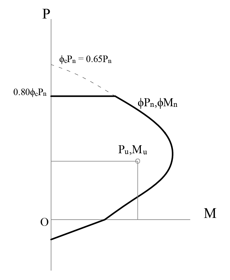
Pn means nominal axial compressive strength, and Mn means nominal flexural strength. Mn takes different values for each axial force level. Therefore, a three-dimensional interaction failure surface is formed in the picture above. Nominal flexural strength Mn is calculated according to the assumptions described in Flexural Strength per ACI 318-19 with ideCAD title. Flexural design strength ϕMn is obtained by calculating Mn and strength reduction factor ϕ at each axial force level. While finding the flexural design strength, combined with axial force ϕMn, it should be found in which control zone the cross-section is. When the section is tension controlled, a ϕ factor for tension control is used. The ϕ factor for compression is used when the section is compression controlled.
As described in the title of Axial strength or Combined Flexural and Axial Strength per ACI 318-19 with ideCAD, for nonprestressed concrete members nominal axial strength Po and the maximum design compressive strength ϕPn,max values are calculated as given below;
'%3e%3cg transform='translate(167%2c0)'%3e%3cg transform='translate(-13%2c0)'%3e%3cg transform='translate(0%2c-6)'%3e%3cuse xlink:href='%23MJMATHI-3D5' x='0' y='0'%3e%3c/use%3e%3cg transform='translate(596%2c0)'%3e%3cuse xlink:href='%23MJMATHI-50' x='0' y='0'%3e%3c/use%3e%3cg transform='translate(642%2c-150)'%3e%3cuse transform='scale(0.707)' xlink:href='%23MJMATHI-6E' x='0' y='0'%3e%3c/use%3e%3cuse transform='scale(0.707)' xlink:href='%23MJMAIN-2C' x='600' y='0'%3e%3c/use%3e%3cuse transform='scale(0.707)' xlink:href='%23MJMATHI-6D' x='879' y='0'%3e%3c/use%3e%3cuse transform='scale(0.707)' xlink:href='%23MJMATHI-61' x='1757' y='0'%3e%3c/use%3e%3cuse transform='scale(0.707)' xlink:href='%23MJMATHI-78' x='2287' y='0'%3e%3c/use%3e%3c/g%3e%3c/g%3e%3cuse xlink:href='%23MJMAIN-3D' x='3638' y='0'%3e%3c/use%3e%3cuse xlink:href='%23MJMATHI-3D5' x='4695' y='0'%3e%3c/use%3e%3cg transform='translate(5291%2c0)'%3e%3cuse xlink:href='%23MJMAIN-30'%3e%3c/use%3e%3cuse xlink:href='%23MJMAIN-2E' x='500' y='0'%3e%3c/use%3e%3cuse xlink:href='%23MJMAIN-38' x='779' y='0'%3e%3c/use%3e%3cuse xlink:href='%23MJMAIN-30' x='1279' y='0'%3e%3c/use%3e%3c/g%3e%3cg transform='translate(7071%2c0)'%3e%3cuse xlink:href='%23MJMATHI-50' x='0' y='0'%3e%3c/use%3e%3cuse transform='scale(0.707)' xlink:href='%23MJMATHI-6F' x='908' y='-213'%3e%3c/use%3e%3c/g%3e%3c/g%3e%3c/g%3e%3c/g%3e%3c/g%3e%3c/svg%3e)
'%3e%3cg transform='translate(167%2c0)'%3e%3cg transform='translate(-13%2c0)'%3e%3cg transform='translate(0%2c-3)'%3e%3cuse xlink:href='%23MJMATHI-50' x='0' y='0'%3e%3c/use%3e%3cuse transform='scale(0.707)' xlink:href='%23MJMATHI-6F' x='908' y='-213'%3e%3c/use%3e%3cuse xlink:href='%23MJMAIN-3D' x='1363' y='0'%3e%3c/use%3e%3cg transform='translate(2419%2c0)'%3e%3cuse xlink:href='%23MJMAIN-30'%3e%3c/use%3e%3cuse xlink:href='%23MJMAIN-2E' x='500' y='0'%3e%3c/use%3e%3cuse xlink:href='%23MJMAIN-38' x='779' y='0'%3e%3c/use%3e%3cuse xlink:href='%23MJMAIN-35' x='1279' y='0'%3e%3c/use%3e%3c/g%3e%3cg transform='translate(4199%2c0)'%3e%3cuse xlink:href='%23MJMATHI-66' x='0' y='0'%3e%3c/use%3e%3cuse transform='scale(0.707)' xlink:href='%23MJMAIN-2032' x='804' y='445'%3e%3c/use%3e%3cuse transform='scale(0.707)' xlink:href='%23MJMATHI-63' x='693' y='-211'%3e%3c/use%3e%3c/g%3e%3cuse xlink:href='%23MJMAIN-28' x='5096' y='0'%3e%3c/use%3e%3cg transform='translate(5486%2c0)'%3e%3cuse xlink:href='%23MJMATHI-41' x='0' y='0'%3e%3c/use%3e%3cuse transform='scale(0.707)' xlink:href='%23MJMATHI-67' x='1061' y='-213'%3e%3c/use%3e%3c/g%3e%3cuse xlink:href='%23MJMAIN-2212' x='6898' y='0'%3e%3c/use%3e%3cg transform='translate(7899%2c0)'%3e%3cuse xlink:href='%23MJMATHI-41' x='0' y='0'%3e%3c/use%3e%3cg transform='translate(750%2c-150)'%3e%3cuse transform='scale(0.707)' xlink:href='%23MJMATHI-73' x='0' y='0'%3e%3c/use%3e%3cuse transform='scale(0.707)' xlink:href='%23MJMATHI-74' x='469' y='0'%3e%3c/use%3e%3c/g%3e%3c/g%3e%3cuse xlink:href='%23MJMAIN-29' x='9337' y='0'%3e%3c/use%3e%3cuse xlink:href='%23MJMAIN-2B' x='9949' y='0'%3e%3c/use%3e%3cg transform='translate(10950%2c0)'%3e%3cuse xlink:href='%23MJMATHI-66' x='0' y='0'%3e%3c/use%3e%3cuse transform='scale(0.707)' xlink:href='%23MJMATHI-79' x='693' y='-213'%3e%3c/use%3e%3c/g%3e%3cg transform='translate(11892%2c0)'%3e%3cuse xlink:href='%23MJMATHI-41' x='0' y='0'%3e%3c/use%3e%3cg transform='translate(750%2c-150)'%3e%3cuse transform='scale(0.707)' xlink:href='%23MJMATHI-73' x='0' y='0'%3e%3c/use%3e%3cuse transform='scale(0.707)' xlink:href='%23MJMATHI-74' x='469' y='0'%3e%3c/use%3e%3c/g%3e%3c/g%3e%3c/g%3e%3c/g%3e%3c/g%3e%3c/g%3e%3c/svg%3e)
Nominal flexural strength Mn with zero compression is calculated as described in the title of Flexural Strength per ACI 318-19 with ideCAD. Similarly, with the same design assumptions, combined nominal flexural and axial strength Mn and Pn are calculated as shown below.
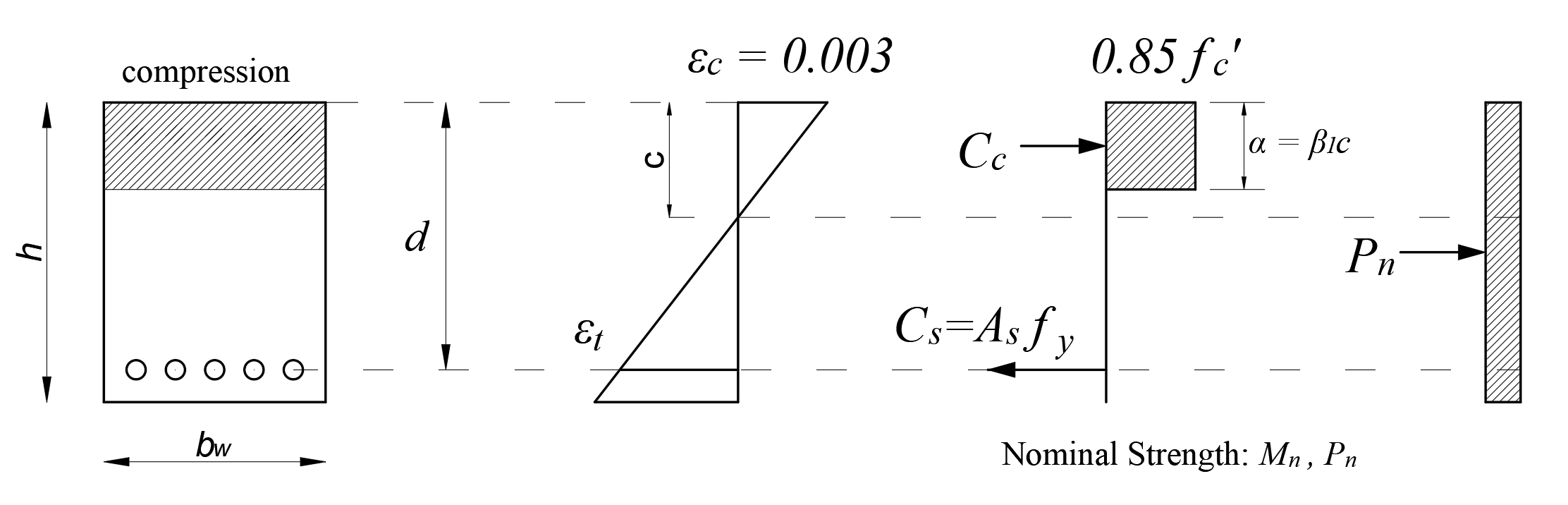
From the equation of equilibrium:
'%3e%3cg transform='translate(167%2c0)'%3e%3cg transform='translate(-13%2c0)'%3e%3cg transform='translate(0%2c-50)'%3e%3cuse xlink:href='%23MJMATHI-50' x='0' y='0'%3e%3c/use%3e%3cuse transform='scale(0.707)' xlink:href='%23MJMATHI-6E' x='908' y='-213'%3e%3c/use%3e%3cuse xlink:href='%23MJMAIN-3D' x='1444' y='0'%3e%3c/use%3e%3cg transform='translate(2501%2c0)'%3e%3cuse xlink:href='%23MJMATHI-43' x='0' y='0'%3e%3c/use%3e%3cuse transform='scale(0.707)' xlink:href='%23MJMATHI-73' x='1011' y='-213'%3e%3c/use%3e%3c/g%3e%3cuse xlink:href='%23MJMAIN-2212' x='3870' y='0'%3e%3c/use%3e%3cg transform='translate(4871%2c0)'%3e%3cuse xlink:href='%23MJMATHI-43' x='0' y='0'%3e%3c/use%3e%3cuse transform='scale(0.707)' xlink:href='%23MJMATHI-63' x='1011' y='-213'%3e%3c/use%3e%3c/g%3e%3c/g%3e%3c/g%3e%3c/g%3e%3c/g%3e%3c/svg%3e)
Nominal flexural strength Mn:
'%3e%3cg transform='translate(167%2c0)'%3e%3cg transform='translate(-13%2c0)'%3e%3cuse xlink:href='%23MJMATHI-4D' x='0' y='0'%3e%3c/use%3e%3cuse transform='scale(0.707)' xlink:href='%23MJMATHI-6E' x='1372' y='-213'%3e%3c/use%3e%3cuse xlink:href='%23MJMAIN-3D' x='1772' y='0'%3e%3c/use%3e%3cg transform='translate(2829%2c0)'%3e%3cuse xlink:href='%23MJMAIN-30'%3e%3c/use%3e%3cuse xlink:href='%23MJMAIN-2E' x='500' y='0'%3e%3c/use%3e%3cuse xlink:href='%23MJMAIN-38' x='779' y='0'%3e%3c/use%3e%3cuse xlink:href='%23MJMAIN-35' x='1279' y='0'%3e%3c/use%3e%3c/g%3e%3cg transform='translate(4609%2c0)'%3e%3cuse xlink:href='%23MJMATHI-66' x='0' y='0'%3e%3c/use%3e%3cuse transform='scale(0.707)' xlink:href='%23MJMAIN-2032' x='804' y='445'%3e%3c/use%3e%3cuse transform='scale(0.707)' xlink:href='%23MJMATHI-63' x='693' y='-211'%3e%3c/use%3e%3c/g%3e%3cuse xlink:href='%23MJMAIN-28' x='5506' y='0'%3e%3c/use%3e%3cg transform='translate(5895%2c0)'%3e%3cuse xlink:href='%23MJMATHI-62' x='0' y='0'%3e%3c/use%3e%3cuse transform='scale(0.707)' xlink:href='%23MJMATHI-77' x='607' y='-213'%3e%3c/use%3e%3c/g%3e%3cuse xlink:href='%23MJMATHI-3B1' x='6931' y='0'%3e%3c/use%3e%3cuse xlink:href='%23MJMAIN-29' x='7572' y='0'%3e%3c/use%3e%3cuse xlink:href='%23MJMAIN-D7' x='8184' y='0'%3e%3c/use%3e%3cuse xlink:href='%23MJMAIN-28' x='9184' y='0'%3e%3c/use%3e%3cuse xlink:href='%23MJMATHI-64' x='9574' y='0'%3e%3c/use%3e%3cuse xlink:href='%23MJMAIN-2212' x='10320' y='0'%3e%3c/use%3e%3cg transform='translate(11098%2c0)'%3e%3cg transform='translate(342%2c0)'%3e%3crect stroke='none' width='572' height='60' x='0' y='220'%3e%3c/rect%3e%3cuse transform='scale(0.707)' xlink:href='%23MJMATHI-3B1' x='84' y='613'%3e%3c/use%3e%3cuse transform='scale(0.707)' xlink:href='%23MJMAIN-32' x='154' y='-562'%3e%3c/use%3e%3c/g%3e%3c/g%3e%3cuse xlink:href='%23MJMAIN-29' x='12133' y='0'%3e%3c/use%3e%3cuse xlink:href='%23MJMAIN-2B' x='12745' y='0'%3e%3c/use%3e%3cg transform='translate(13746%2c0)'%3e%3cuse xlink:href='%23MJMATHI-50' x='0' y='0'%3e%3c/use%3e%3cuse transform='scale(0.707)' xlink:href='%23MJMATHI-6E' x='908' y='-213'%3e%3c/use%3e%3c/g%3e%3cuse xlink:href='%23MJMAIN-D7' x='15135' y='0'%3e%3c/use%3e%3cuse xlink:href='%23MJSZ2-28' x='16136' y='-1'%3e%3c/use%3e%3cg transform='translate(16733%2c0)'%3e%3cg transform='translate(120%2c0)'%3e%3crect stroke='none' width='527' height='60' x='0' y='220'%3e%3c/rect%3e%3cuse transform='scale(0.707)' xlink:href='%23MJMATHI-68' x='84' y='613'%3e%3c/use%3e%3cuse transform='scale(0.707)' xlink:href='%23MJMAIN-32' x='122' y='-562'%3e%3c/use%3e%3c/g%3e%3c/g%3e%3cuse xlink:href='%23MJMAIN-2212' x='17723' y='0'%3e%3c/use%3e%3cuse xlink:href='%23MJMAIN-28' x='18724' y='0'%3e%3c/use%3e%3cuse xlink:href='%23MJMATHI-68' x='19113' y='0'%3e%3c/use%3e%3cuse xlink:href='%23MJMAIN-2212' x='19912' y='0'%3e%3c/use%3e%3cuse xlink:href='%23MJMATHI-64' x='20913' y='0'%3e%3c/use%3e%3cuse xlink:href='%23MJMAIN-29' x='21436' y='0'%3e%3c/use%3e%3cuse xlink:href='%23MJSZ2-29' x='21826' y='-1'%3e%3c/use%3e%3c/g%3e%3c/g%3e%3c/g%3e%3c/svg%3e)
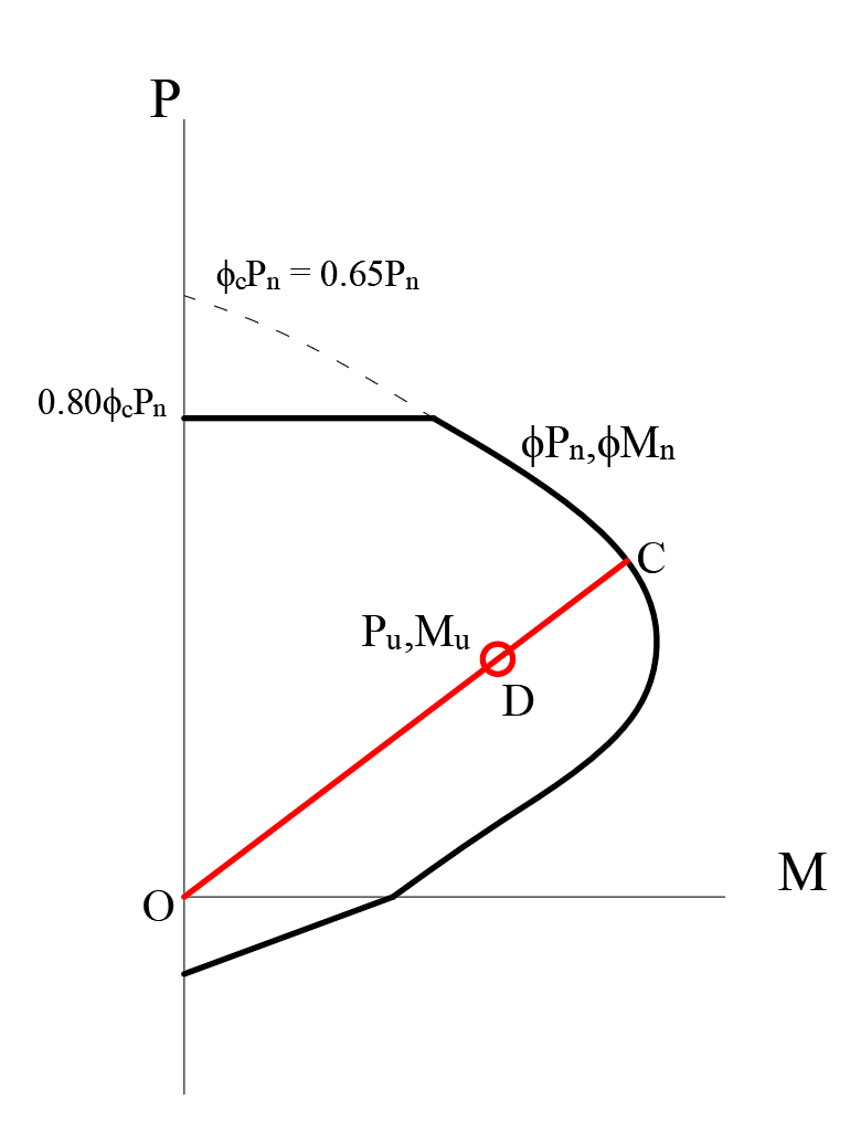
Demand/Capacity Ratio of Columns
Because of the axial force and biaxial bending interaction in the columns, the demand/capacity ratio is calculated using the interaction curve. The point (Pu,Mu) is placed in the interaction space shown as point D in the picture below. If point D (Pu,Mu) is within the acceptable range, the column capacity is adequate. However, if the point D (Pu,Mu) is outside the interaction volume, the column is overstressed. The capacity ratio is calculated using point C obtained by extending the line passing through points O and D to the interaction curve. The capacity ratio is given by the ratio OD/OC.