
How does ideCAD control width-to-thickness Ratios according to AISC 341-16?
The width-to-thickness ratios of steel elements are automatically controlled and reported with steel elements reports according to Table D1.1.
Symbols
Fy = Specified minimum yield stress
Ry = Ratio of the expected yield stress to the specified minimum yield stress, Fy
Rt = Ratio of the expected tensile strength to the specified minimum tensile strength, Fu
Pa = Required axial strength using ASD load combinations, kips (N)
Pu = Required axial strength using LRFD load combinations, kips (N)
Py = Axial yield strength, kips (N)
Ca = Ratio of required strength to available axial yield strength
E= Modulus of elasticity of steel = 29,000 ksi (200 000 MPa)
Local buckling, when repeated like low-cycle fatigue caused by an earthquake, can cause very high localized stresses that can cause premature failure of an element intended to behave in a ductile manner. In order for horizontal structural system elements to achieve sufficient plastic deformation without local buckling under the effects of earthquakes, the width-thickness ratios of the compression elements must meet the conditions given in Table D1.1.
The width-to-thickness ratios of steel elements are automatically controlled and reported with steel elements reports according to Table D1.1.
|
Limiting Width-to-Thickness Ratios for Compression Elements for Moderately Ductile and Highly Ductile Members |
||||
|---|---|---|---|---|
|
Description of Element |
Width-to- Thickness Ratio |
Limiting Width-to-Thickness Ratio |
Example |
|
|
λhd
|
λmd
|
|||
|
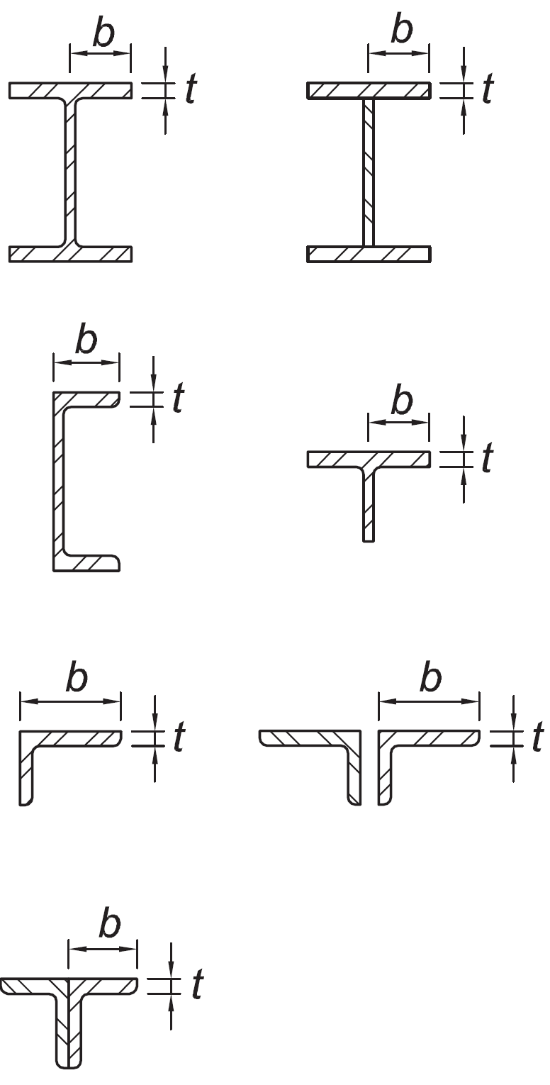
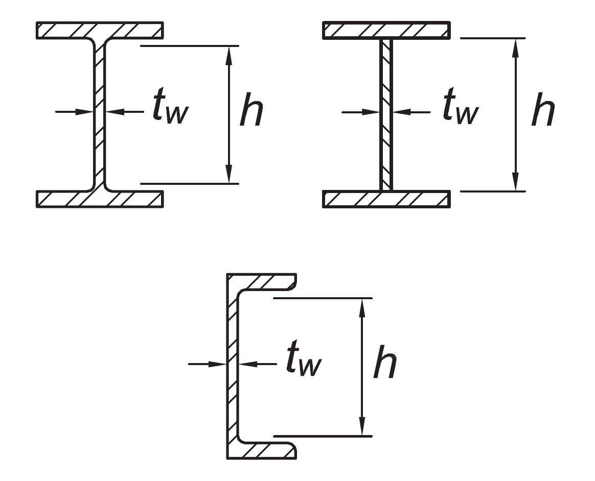
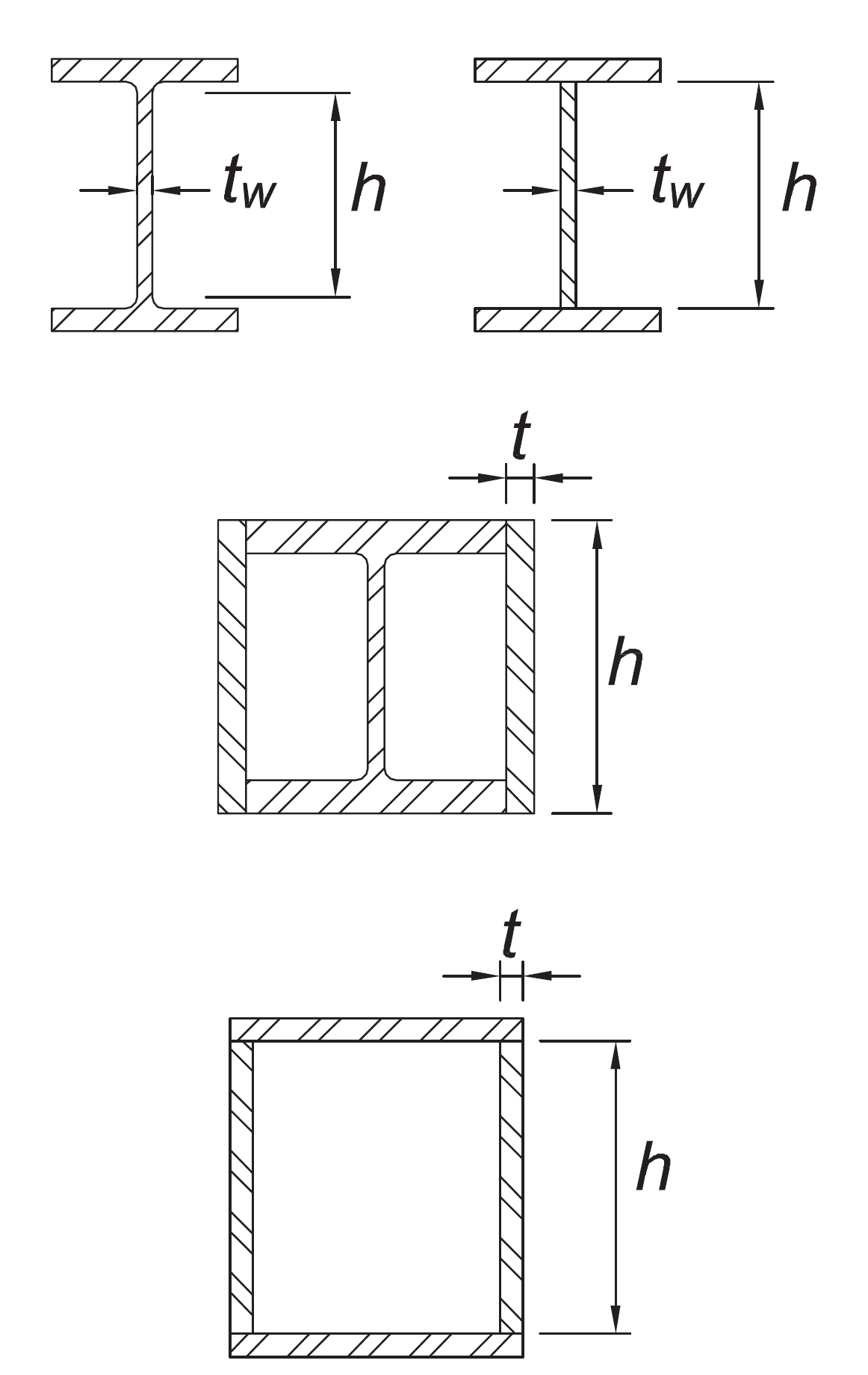
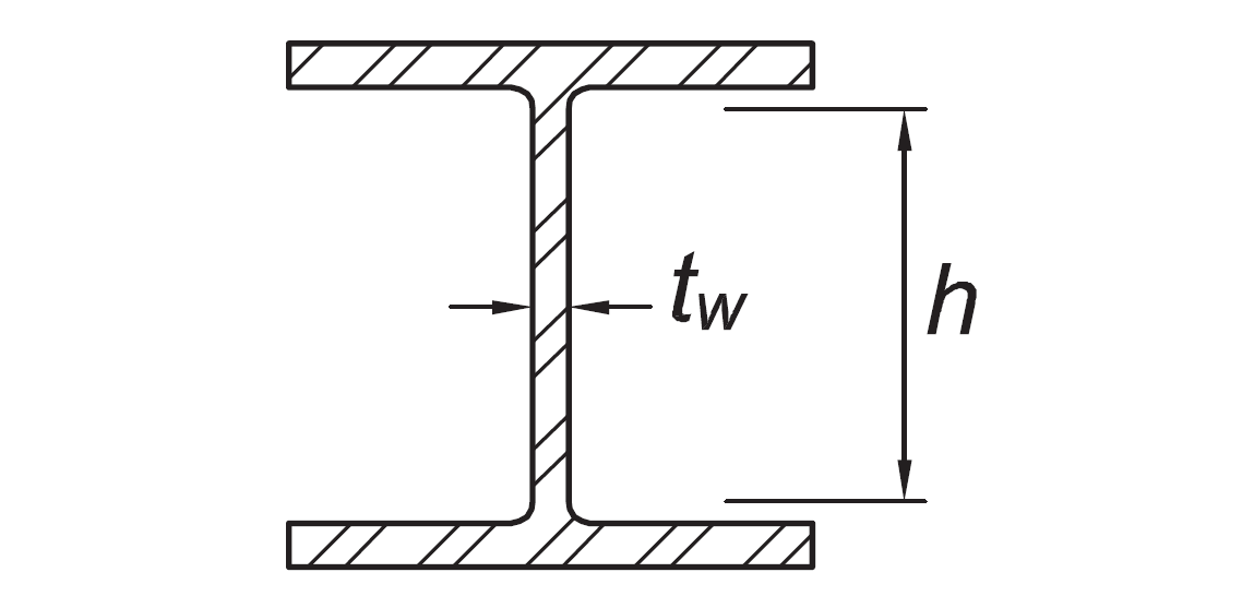
Flanges of rolled or built-up I-shaped sections, channels and tees; legs of single angles or double-angle members with separators; outstanding legs of pairs of angles in continuous contact |
b/t |
|
|
|
|
Flanges of H-pile sections per Section D4 |
b/t |
not applicable |
|
|
|
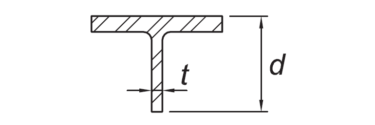
Stems of tees |
d/t |
|
|
|
|
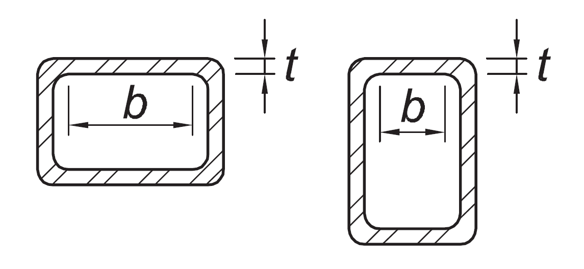
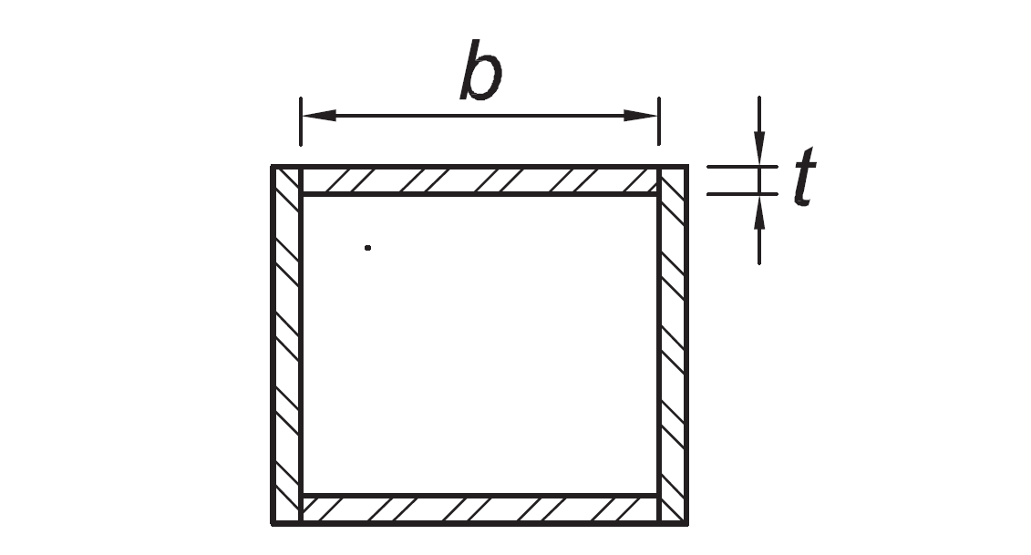
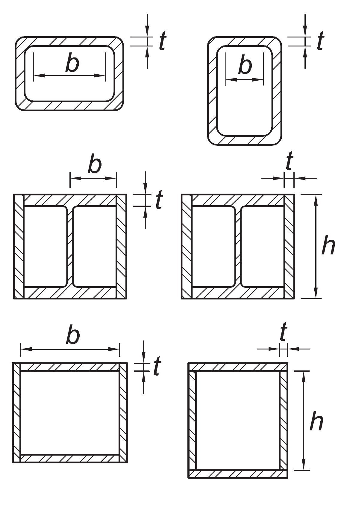
Walls of rectangular HSS used as diagonal braces |
b/t |
|
|
|
|
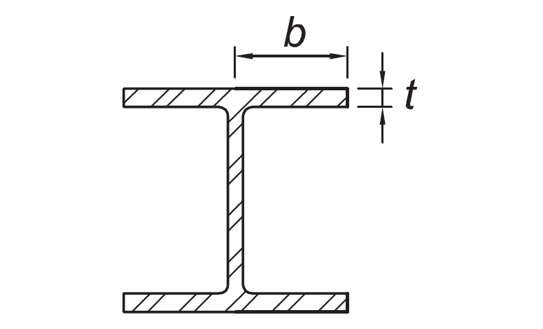
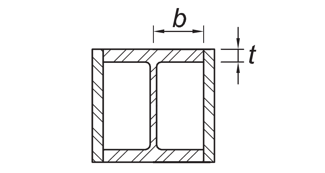
Flanges of boxed I-shaped sections |
b/t |
|
|
|
|
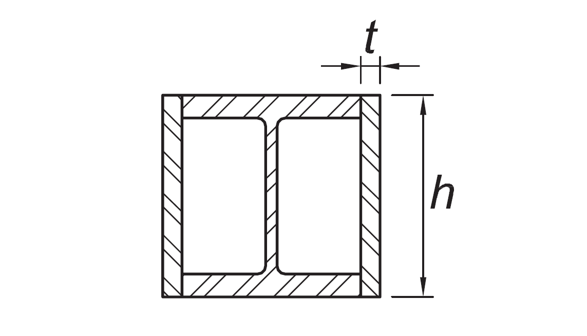
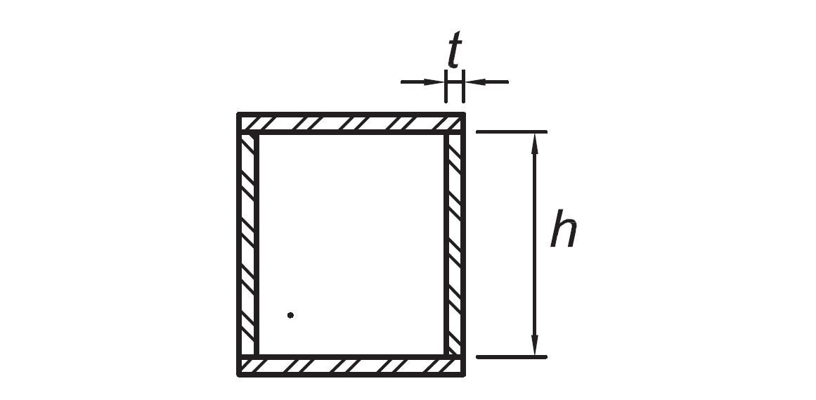
Side plates of boxed I-shaped sections and walls of built-up box shapes used as diagonal braces |
h/t |
|
|
|
|
Flanges of built up box shapes used as link beams |
b/t |
|
|
|
|
Webs of rolled or built-up I shaped sections and channels used as diagonal braces |
hw/t |
|
|
|
|
Where used in beams or columns as flanges in uniform compression due to axial, flexure, or combined axial and flexure:
|
b/t
h/t |
|
|
|
|
Where used in beams, columns, or links, as webs in flexure, or combined axial and flexure:
|
h/tw
h/t
h/t |
For Ca ≤ 0.114
For Ca > 0.114
where
|
For Ca ≤ 0.114
For Ca > 0.114
where
|
|
|
Webs of built-up box sections used as EBF links |
h/t |
|
|
|
|
Webs of H-Pile sections |
h/tw |
not applicable |
|
|
|
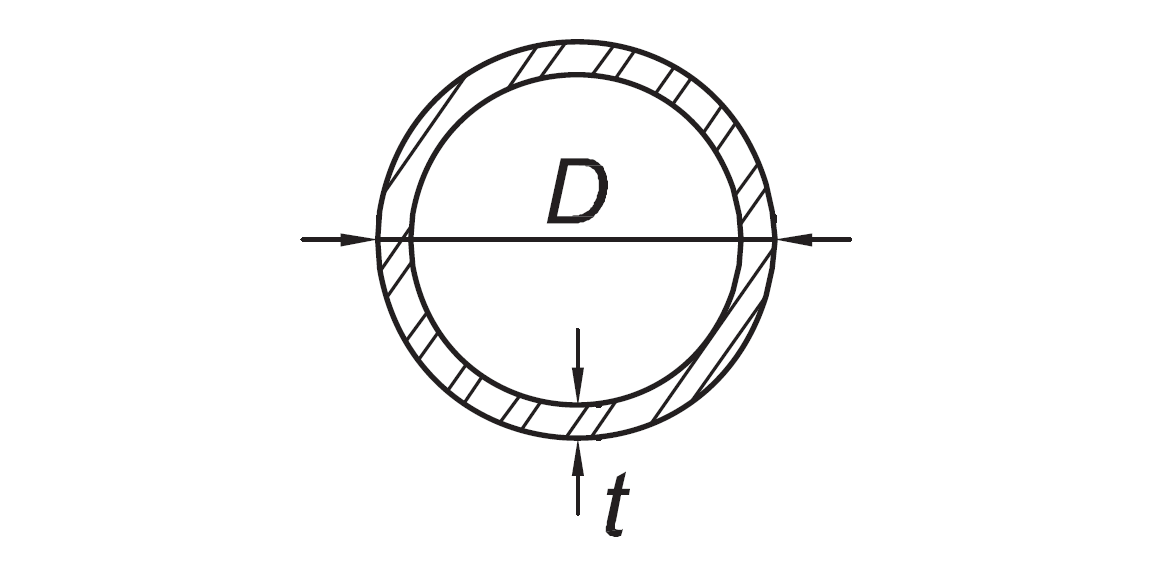
Walls of round HSS |
D/t |
|
|
|
Next Topic