-
In each step of the thrust analysis, the modal pseudo acceleration, modal displacement increment and cumulative scale coefficient are automatically determined.
ARSA method is a displacement controlled pushover analysis method. In the method, the modal displacement increments are scaled according to the nonlinear spectral displacement value obtained according to the instantaneous dynamic characteristics of the structure. In the previous step, in order to find the modal scaling value in each nth vibration mode, the elastic spectral displacement of the system, the value from S (1), was found by using the equidistant displacement rule.
The modal displacement (displacement) increment, d n (i), is found by the equation shown below. The index "n" in the term Δd n (i) indicates the mode in which mode and the index (i) indicates the step in which step is processed.
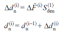
In step (i), it expresses the constant incremental spectrum scale coefficient for all modes. Thus, the modal displacement increments in each repulsion step are expressed depending on a single parameter. Since it is a scale factor, this value must be calculated in order to proceed to the next pushing step.
:art_ölç_kat::art_ölç_kat:
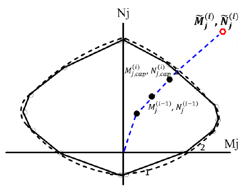
In order to calculate this value, as a result of the linear (linear) mode combination analysis performed in the i'th step of the structure, The typical value of displacement, plastic deformation or internal force calculated at any point (j) or section must be found. This value is also It also means the value calculated by taking = 1. value represents internal force, strain, displacement, or plastic rotation of all points in the structure. In order to find the plastic hinge formation point, the axial force and moment values in both axes must be found at all defined points of the plastic hinge. In any i'th step Normal force value from internal force values at any point (j) made by modal combination method by taking = 1 The moment in the (x) axis and the moment in the (y) axis anyway. The normal force value calculated in the previous step is represented as N j (i-1) , the moment M j on the (x) axis, the moment M j on the x (i-1) and (y) axis M j, y (i-1) . In this case, at any j potential plastic cross section, the obtained for all (k) yield surfaces its value is shown below.
:art_ölç_kat::My_cizgi_ij::Mx_cizgi_ij::N_cizgi_ij::art_ölç_kat::r_cizgi_ij::art_ölç_kat::r_cizgi_ij:
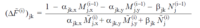
Here the coefficients α and are the coefficients required to find the yield surface of the element and are a coefficient of the interaction equation of axial force and biaxial bending. Instead of establishing this equation, a three-dimensional interaction curve obtained by moment-curvature analysis can be used. In this case, the flow surfaces can be determined and the incremental spectrum scale coefficient can be calculated. If the flowing surface is exceeded, it means that there has been a plasticization at this point.
Cumulative scale coefficient, value is calculated for all (j) points in the i th step and the minimum value is used for all modes.
:art_ölç_kat::art_ölç_kat:
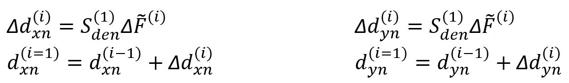
S from (1) andAfter finding (i) th thrust step n-th mode of spectral displacement increments expressed as a dimensionless n (i) and (ii) th push the end of stage n-th mode of spectral displacement d n (i) values are determined by the following equations. However, these values must be found for each direction. In an example (X) direction, the modal displacement increment of the n'th mode in the (i) th push step Δd xn (i) and the modal displacement of the n'th mode at the end of the (i) th push step is expressed as d xn (i) . . Similarly, the same expressions for direction (Y) are Δd yn (i) and d yn (i), respectively.It is expressed as. These values are found by the following equations.
:art_ölç_kat:
A sample (X) direction, Δα xn (i) (i) th step and modal acceleration increments the all modes (i) th thrust cumulative spectral acceleration value at the end of step α xn (i) is as indicated. Similarly, for the (Y) direction, the modal acceleration increments of all modes in inciα yn (i) step (i) and the cumulative modal acceleration value at the end of the (i) th thrust step are expressed as α yn (i) . These values are found by the following equations.
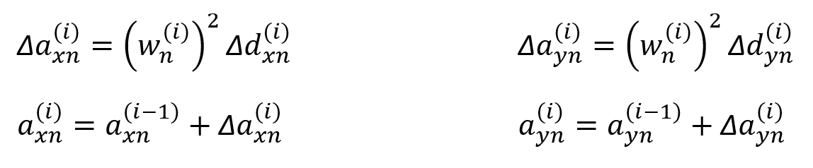
ω n (i) means the natural angular frequency of the nth vibration mode in the (i) th thrust step, determined by considering the plastic cross section configuration in that step. It is obtained from the dynamic analysis results made in the (i) step.
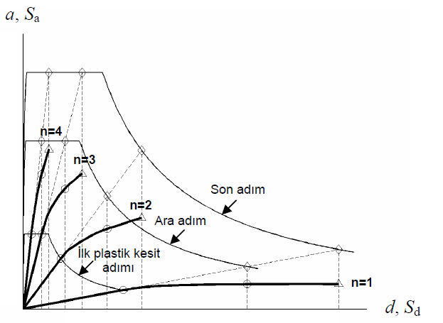
Typical modal capacitance diagrams where modal displacements on the horizontal axis, d n (i) and modal accelerations on the vertical axis, α n (i) are represented are shown in the figure below.
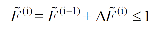
The cumulative spectrum scale coefficient calculated at the end of each i th thrust step, It is checked whether it exceeds the unit value with the highest value. If it does not exceed, the analysis continues.
:f_cizgi_i: