
In concrete elements;
Column and beam elements are modeled with rod finite elements, considering all 6 degrees of freedom at the nodal points. Shearwalls and slabs are modeled with shell finite elements (shell) containing degrees of freedom for both in-plane and out-of-plane displacements. At the nodes of shell finite elements, all 6 degrees of freedom are taken into account.
The flexible diaphragm model is the analytical model that represents the situation where slab stiffness is taken into account. The stiffness calculation is calculated depending on the slab thickness, dimensions and material parameters. The flexible diaphragm acceptance is the one that reflects the most realistic behavior of the slab behavior in the structure analysis model. In the flexible diaphragm model, slabs are modeled with Local Axes of Shell Elements. Local axes of shell elements can move in-plane out-of-plane and create stresses on the shell element. Concrete slab design can be made according to this stress distribution .
Beam Finite Elements
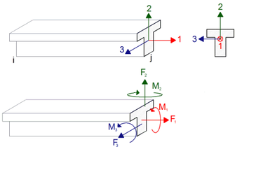
The internal forces of the beam finite elements (columns and beams) as a result of the analysis are shown according to the local beam axis (local axis) direction assumption. A bar element with 3D analysis has 3 local axes. These local axes may vary according to the position and placement of the bar. An exemplary view of local axes in beam elements is shown in the figure below.
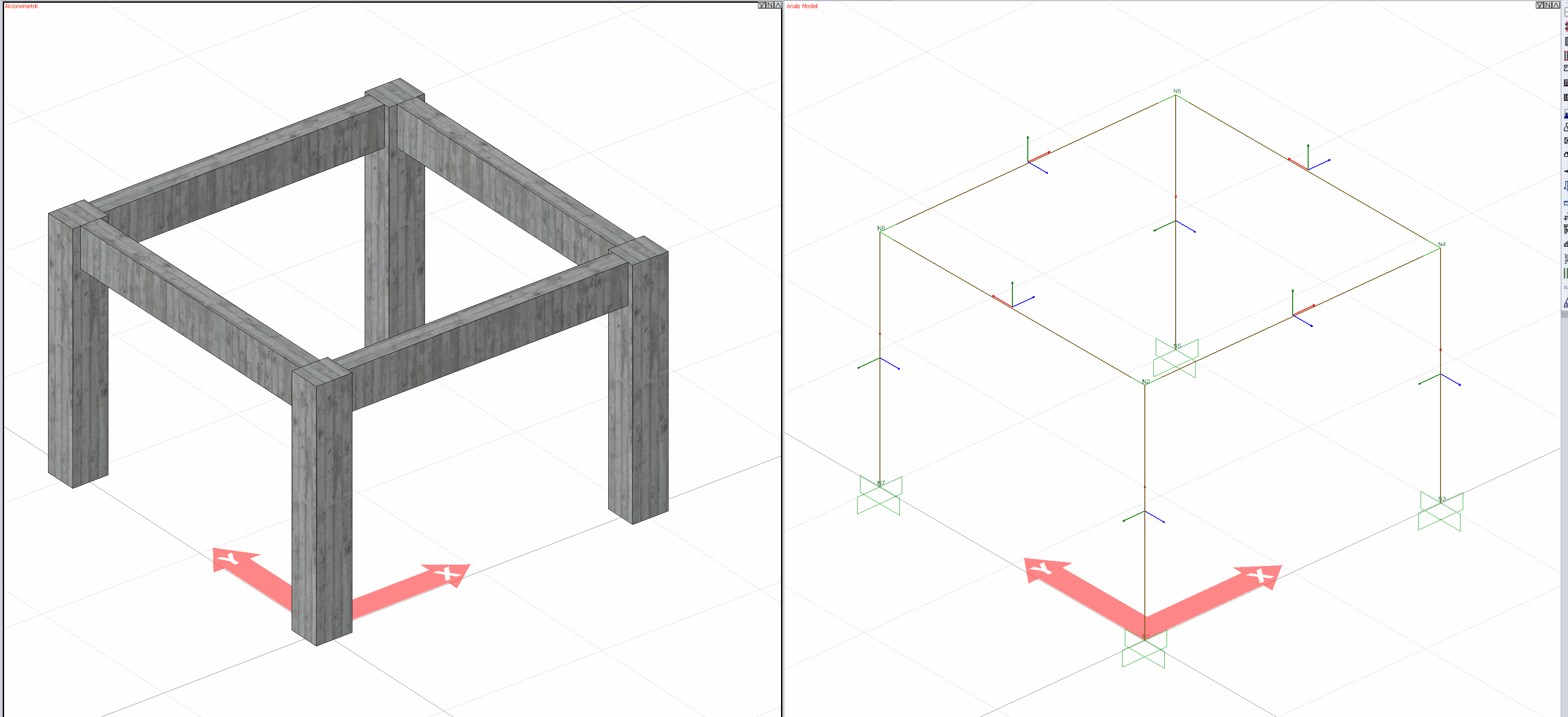
The relationship between the numbers and colors of the local axes in the beam elements is as follows.
1 direction - Red
2 direction - Green
3 direction - Blue
There are 6 degrees of freedom in a cross-section of a bar element for which three-dimensional analysis is performed. These are translations in directions 1,2 and 3 and rotations about 1,2 and 3.
For detailed information; Element Local Axes
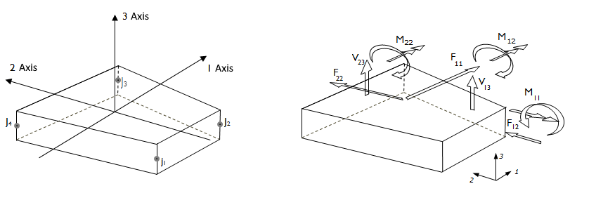
Shell Finite Elements
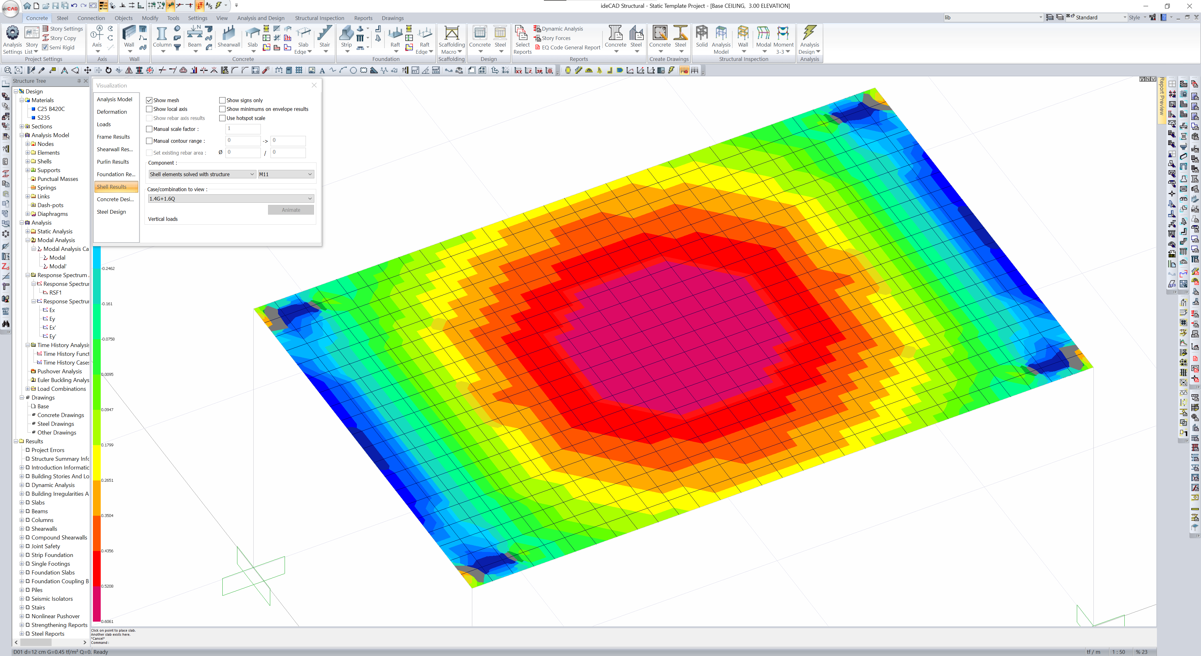
As a result of three-dimensional analysis of shell finite elements (slabs, shearwalls and polygon shearwalls), they generate stresses and forces per unit length. The directions of these stresses and forces per unit length are determined according to the local axes of the shell finite element.
Shell finite element forces are obtained as a result of stresses formed by shell finite elements in three-dimensional analysis.
The analysis results of a structure with slabs and shearwalls modeled with shell finite elements can be seen as follows.
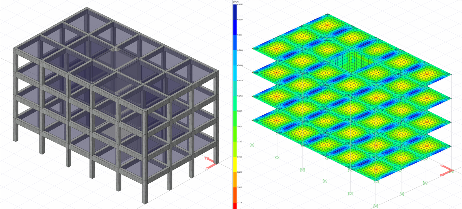
For detailed information; Local Axes of Shell Elements
Beam and Shell Finite Element Connections
In the analysis model established for the flexible diaphragm solution, the beams are included in the analysis system with the rigidities of the defined dimensions. In beams connected with slabs; An analysis model is created by dividing the beam finite element representing the beam from the nodal points of the shell elements representing the story. In this way, it is ensured that the slabs and beams enter the analysis model as a whole and with the required rigidity.
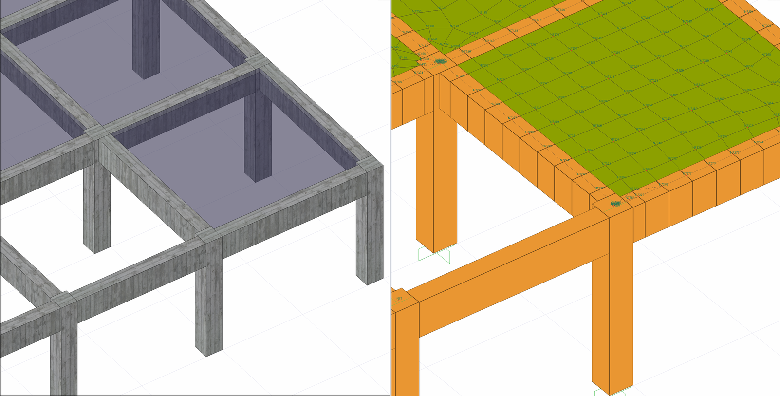
In the flexible diaphragm analysis model, no table section is accepted for beam elements. Because two-dimensional finite elements will be attached to the beam element, causing an increase in the stiffness matrix of the beam element. In this case, the table beam effect is given by shell finite elements.
While the analysis model of the slab, beam, column and shearwall concrete elements is created, the nodal points of the bar and shell finite elements are automatically connected.
Green Link Elements
It connects concrete columns and beams along their long axis. The length of the link element is automatically defined in accordance with the column-beam layout, taking into account the column dimensions and misalignment in the column-beam junction area.
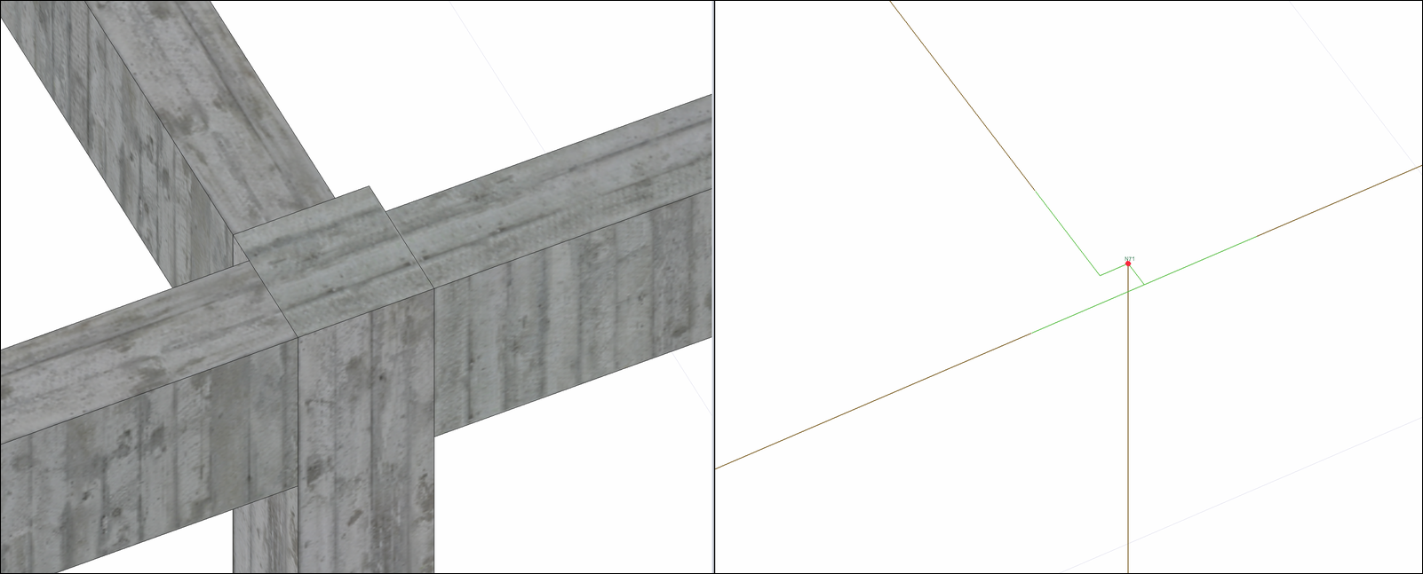
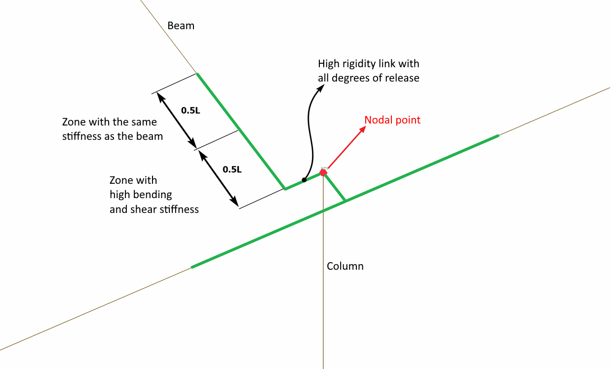
In the green link element defined on the concrete beam axis, half of the link length in the continuation of the beam has the same stiffness values as the beam, and the remaining half of the length has very high bending and shear stiffness. In the section with high stiffness, the moment in the 3 direction and the shear stiffness in the 2 direction have high values relative to the local axis of the beam. In case of misalignment, stiffnesses in all directions are defined as high (infinite) value. The picture below illustrates this situation. The length L is defined as the length of the link element.
Red Link Elements
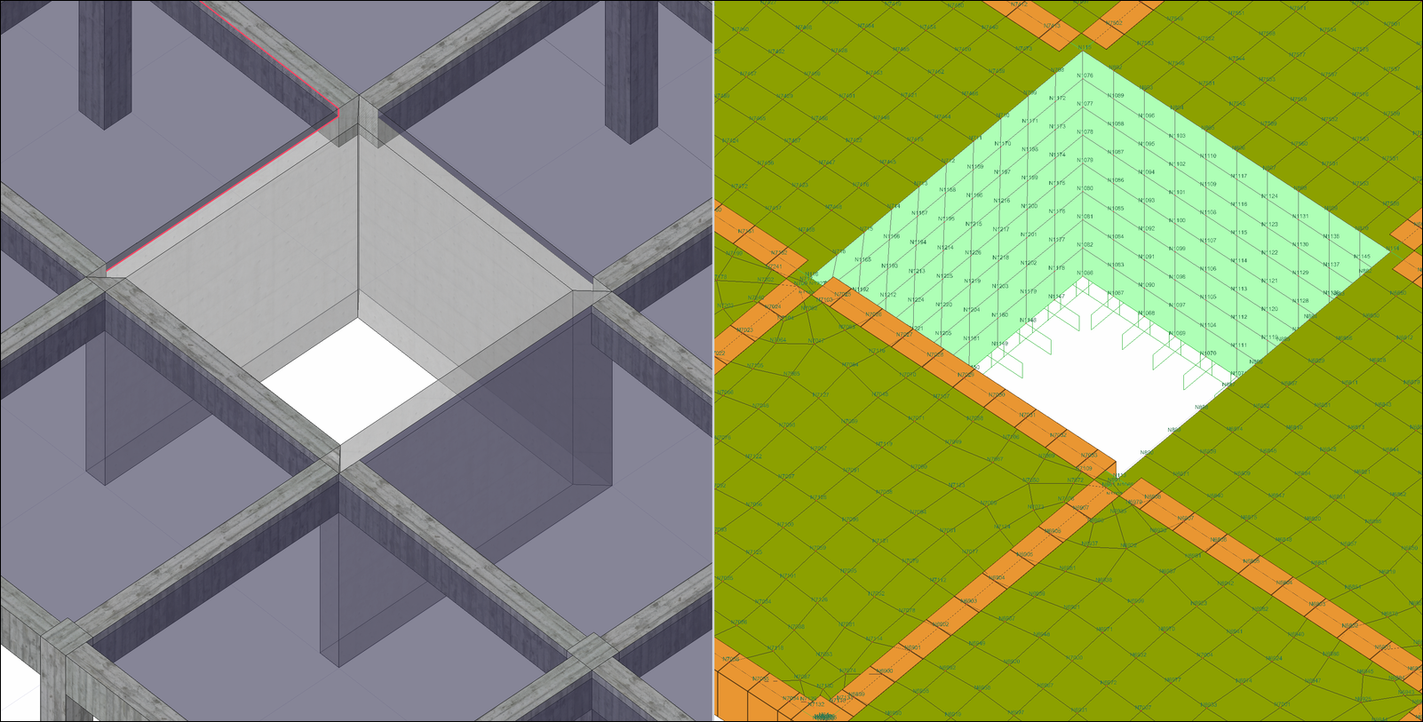
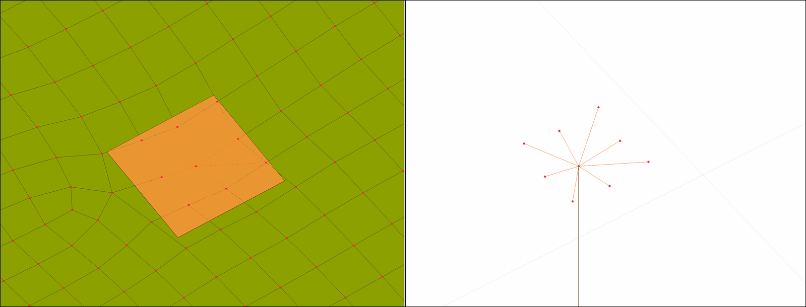
The connection of concrete slabs with concrete columns is formed with red colored rigid link elements, taking into account the column dimensions and misalignment. Red link elements are used to connect the joint points of the two-dimensional finite elements (shell) where the slabs are defined and the joint points of the bar elements where the columns are defined. All degrees of freedom of these connections have high (infinite) stiffness.
The image below shows column-to-slab connections for beamless slab. In the sections where the slabs converge to the columns, finite element compatibility with the column is created. The nodal points of the shell elements entering the column area are connected to the column node with the red link element.
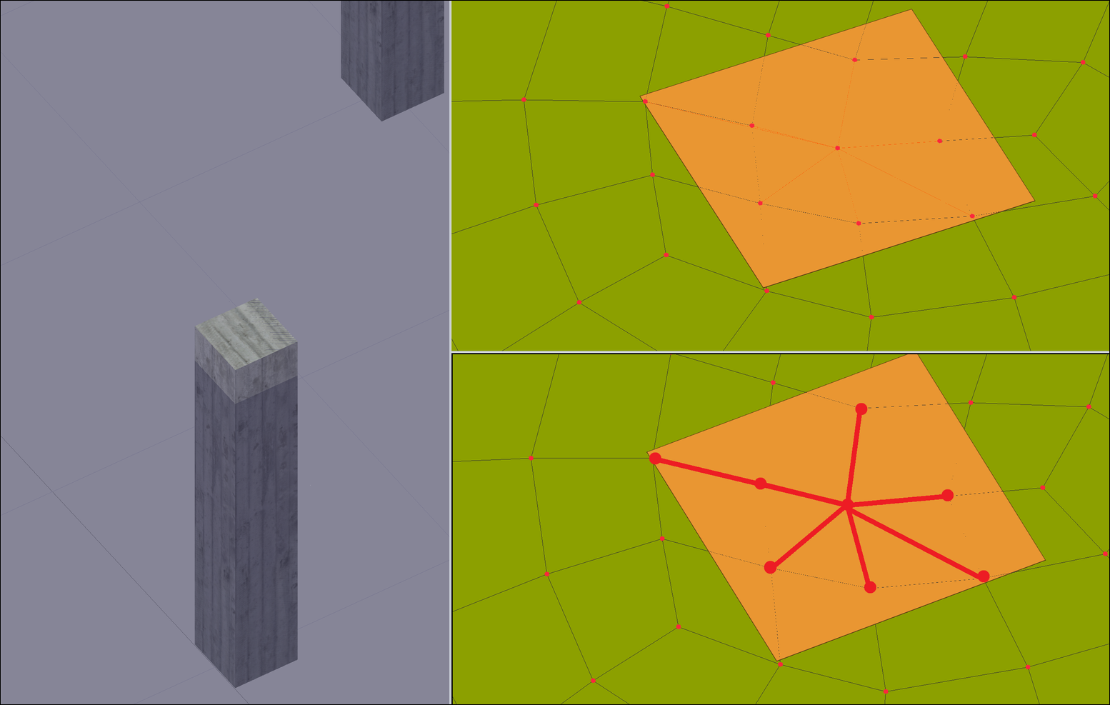
As the finite element widths are reduced, the linked link elements will also increase.
Next Topic