
Symbols
Ag : Gross cross-sectional area of member
Cw : Warping constant, in.6 (mm6)
E: Structural steel modulus of elasticity
Fcr : Critical stress
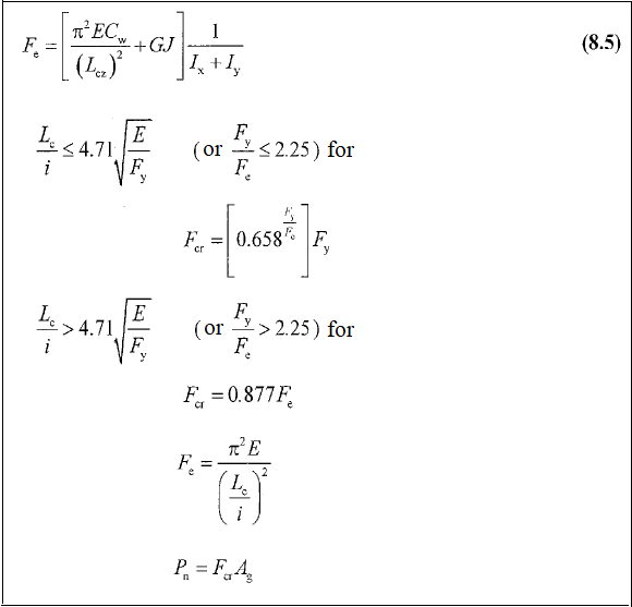
Fe : Elastic buckling stress determined according to Equation 8.5
Fy : Specified minimum yield stress of the type of steel being used
G: shear modulus of elasticity of steel = 11,200 ksi (77 200 MPa)
J: Torsional constant, in.4 (mm4)
K : Effective length factor
L: Laterally unbraced length of the member
Lcz : Effective length of member around the z-axis (= KL)
Ix , Iy : Moment of inertia about the principal axes, in.4 (mm4)
i: Radius of inertia
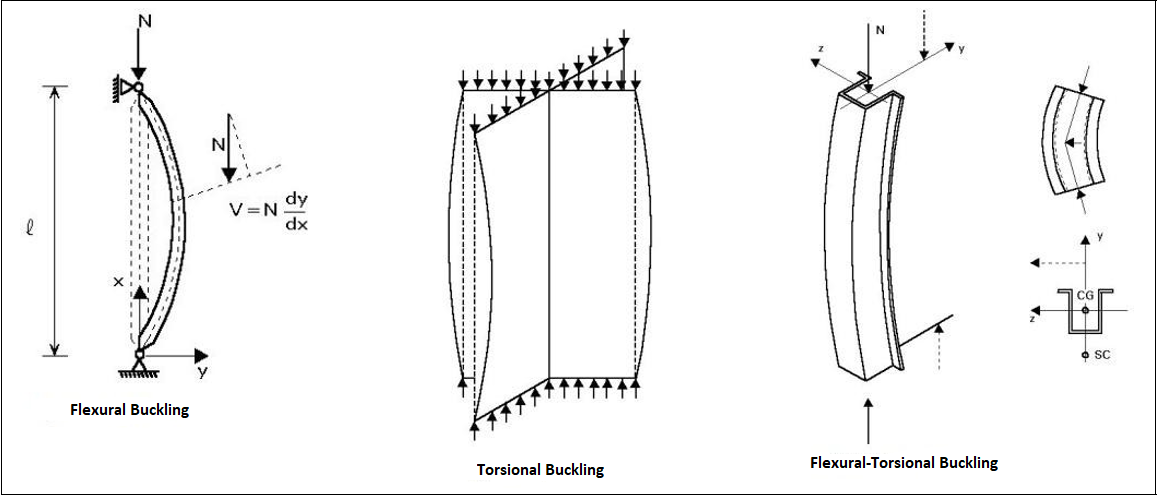
Torsional Buckling Limit State
-
Buckling occurs when the element rotates around its longitudinal axis. It occurs in positive (+) shaped built-up elements or channel cross-section that are compressive elements consisting of 4 equal leg angle placed back to back.
Design with ÇYTHYE 2018
-
The compressive strength of the elements is determined according to the axial force acting into the center of gravity section.
-
The torsional buckling limit state occurs when the element rotates around its longitudinal axis (positive (+) shaped built-up elements or channel cross-section that are compressive elements consisting of 4 equal leg angle placed back to back) and the elastic buckling stress F e is calculated by equation 8.5.
Next Topic