
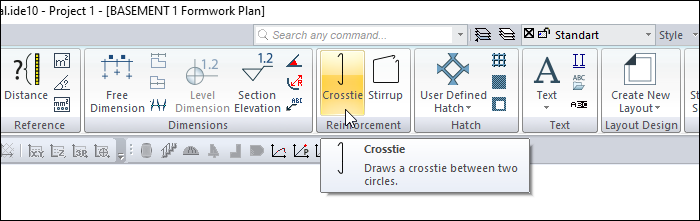
The ideCAD automatically draws crosstie in the columns in accordance with the standards specified in the earthquake regulations. However, the user can draw crosstie according to the need - this need may arise in polygon columns - with a crosstie draw.
Location of the Crosstie Command
You can access it under the Drawings tab, Reinforcement heading.
Usage Steps
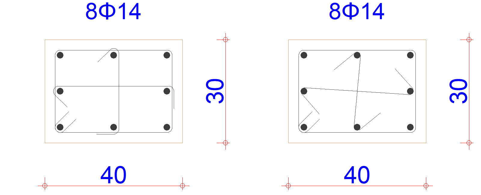
For example, let's cancel the crossties in the left column above and draw crossties as seen in the right column.
-
In the column application plan, explode the column with the explode command.
-
Erase the crossties.
-
Click on the crosstie icon.
-
Click the two longitudinal reinforcements you want to draw crosstie in the polygon column with the left click.
-
Press the spacebar to change the position of the crosstie.
-
Click the left mouse button to complete the drawing.
|
Usage step |
|---|
|
The first version of the column drawing 
|
|
Erasing the crosstie 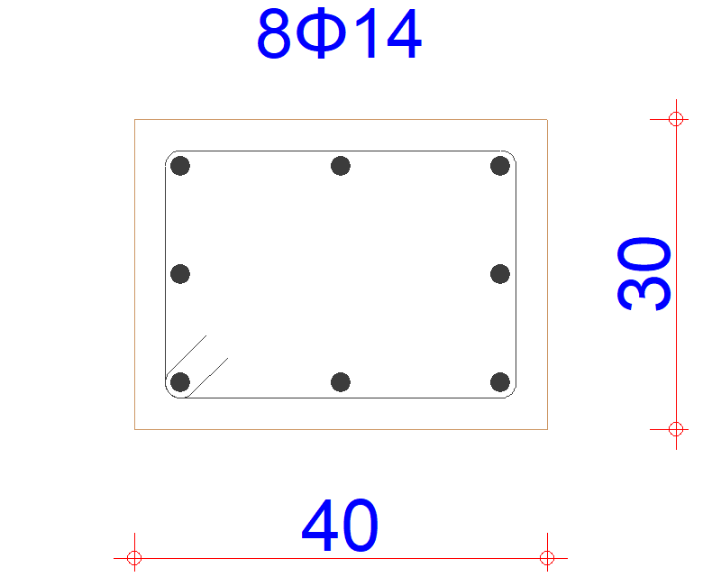
|
|
Selection of the first point of the first crosstie 
|
|
Choosing the second point 
|
|
Changing the position with the spacebar and the formation of crosstie 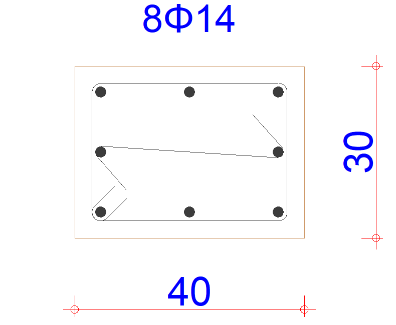
|
|
Selection of the first and second point of the second crosstie 
|
|
Changing the position with the spacebar and the formation of crosstie 
|
Next Topic