
The formwork plan section will be prepared automatically while creating the formwork plan, or after the formwork plan is created, the section line can be created in the wanted number. Automatic creation of the formwork plan section while receiving the formwork plan depends on the formwork plan section option in the Drawing Properties dialog.
With the formwork plan drawing, new section lines can be defined in the desired number and direction, even if the formwork plan sections are prepared automatically. Using section lines, sections are placed at a desired location in the drawing. The formwork plan section lines are used in the formwork plan window.
Location of the Formwork Plan Command
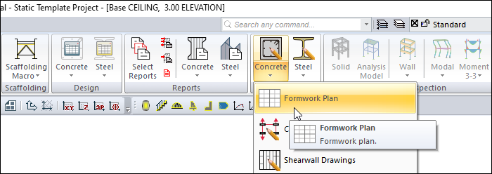
You can access it under the ribbon menu Concrete tab, Create Drawing heading.
Location of the Structural Section Command
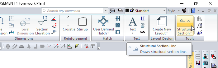
You can access it under the Drawings tab, Tools heading.
Usage Steps
-
Click the Formwork Plan command to create the formwork plan .
-
The Drawing Properties dialog will open.
-
Click the Advanced Settings tab.
-
Check the option Add structural section .
-
If you do not want the structural section to be created automatically, uncheck it.
-
When you click the OK button, your choice will be processed and your formwork plan will be created.
-
Click on the line Structural Section Line under the tools heading of the Drawings tab .
-
Move the cursor to the location you want to section and click any point with the left mouse button.
-
The first point of the section line will appear. Slide the cursor at a specific angle. Click the left button again at a sufficient distance.
-
At this stage, you can create a stepped section line by clicking the left button again.
-
After the section line is drawn, press the Enter key on the keyboard. (The mouse cursor will become an eye)
-
To specify the viewing direction of the section line, move the cursor above or below the section line and left click.
-
The preview of the section will appear. The preview moves perpendicular to the drawn section line.
-
Move the preview to the appropriate position and click the left mouse button.
-
The section will be formed.
|
Usage step |
|---|
|
Formwork plan 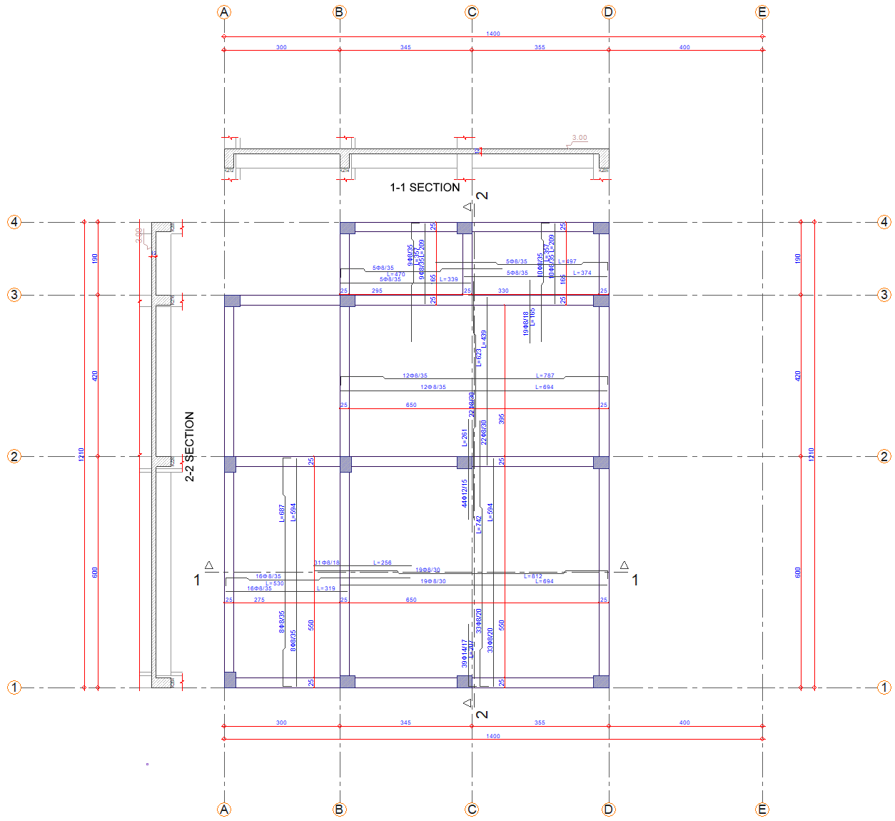
|
|
Determining the first point for the new section line 
|
|
Determination of the second point 
|
|
Determining the viewing direction 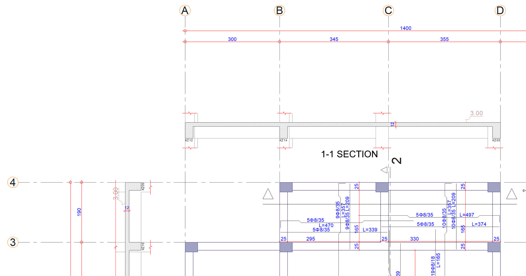
|
|
Previewing the new section, determining the section location 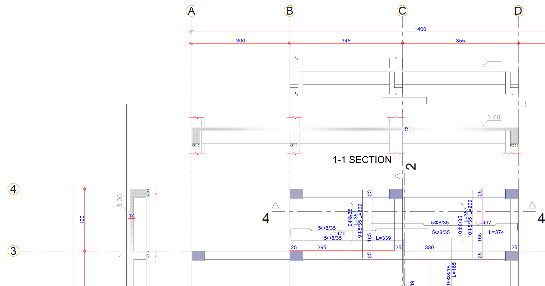
|
|
Creation of new section 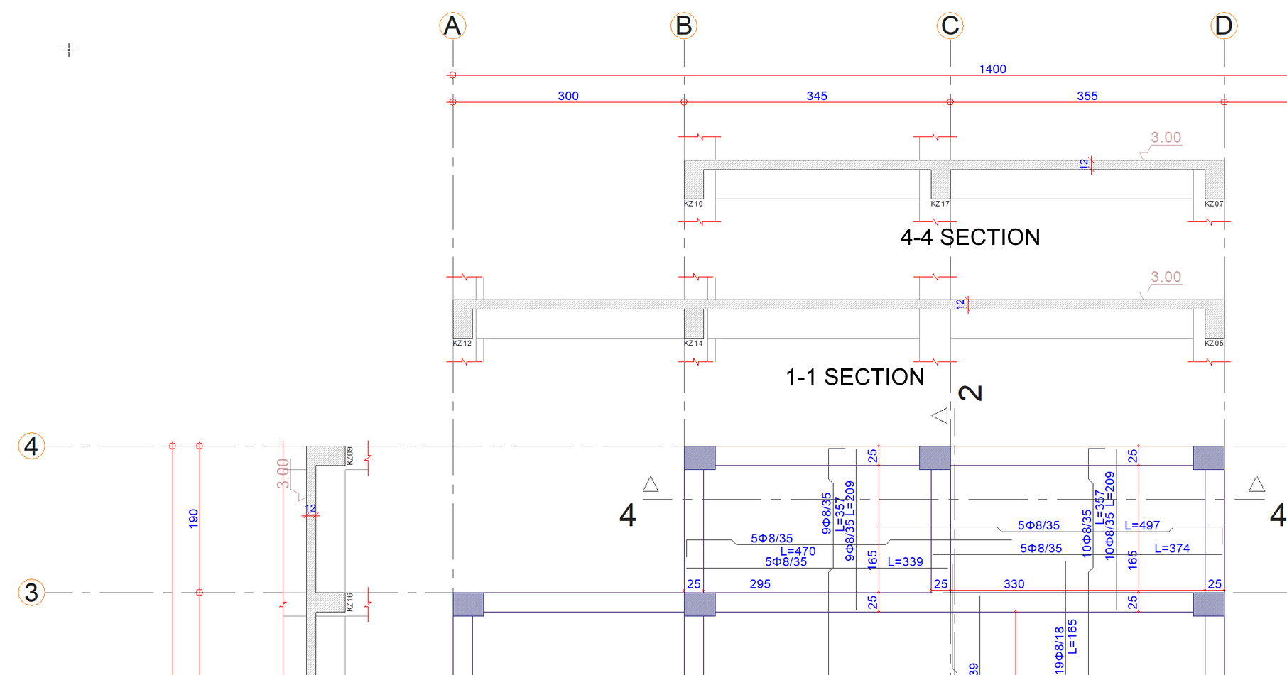
|
|
Formwork plan with section added 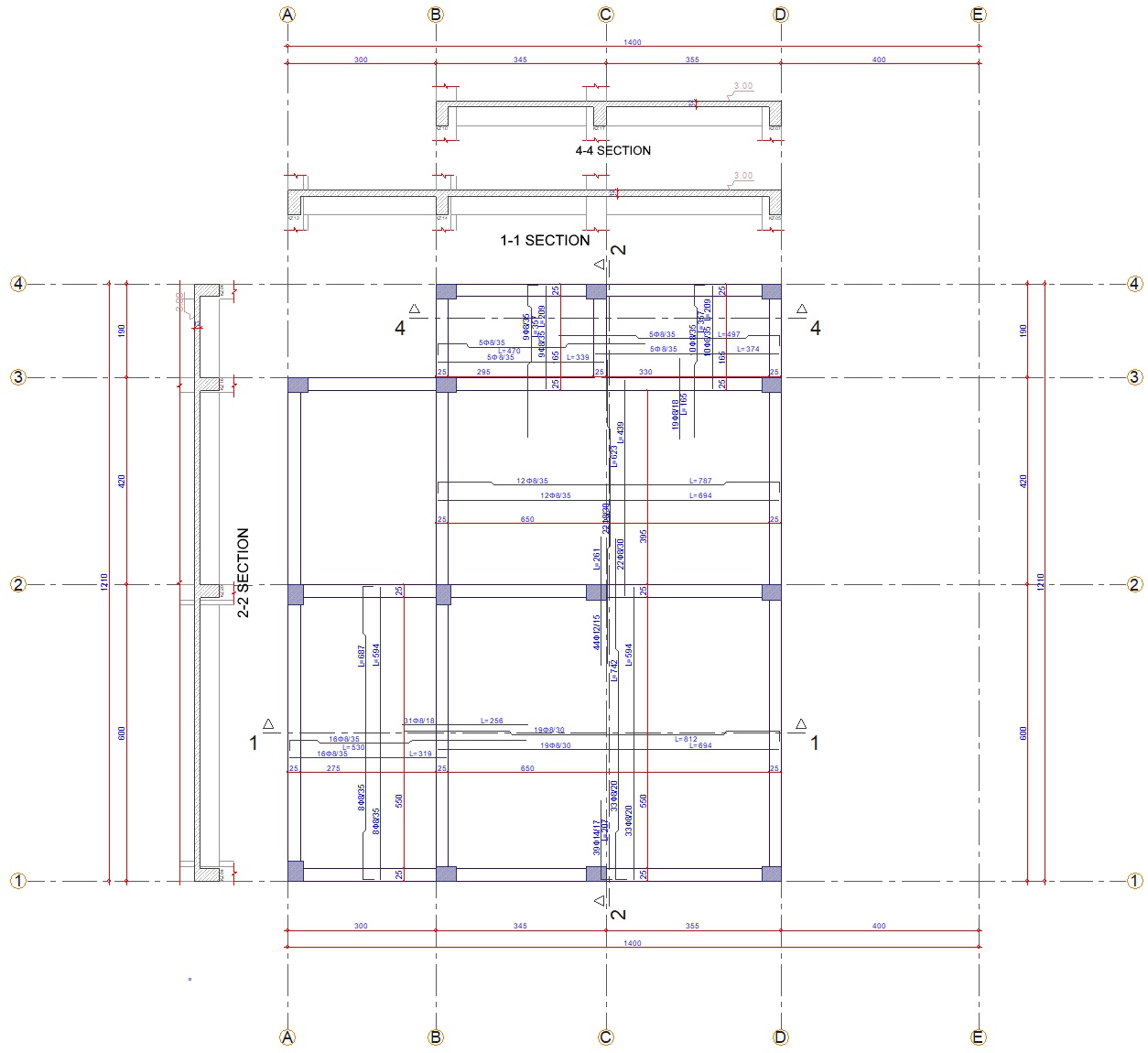
|
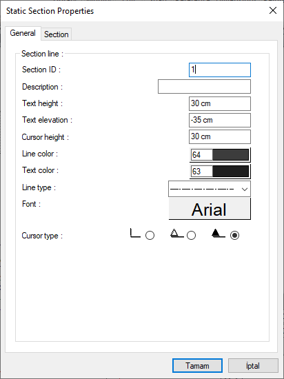
Static Section Properties
The properties of the prepared sections are determined with the information given in the Static Section Properties dialog. In order to transfer the changes made in the static section properties to the existing section, the section must be relocated.
You can access the section properties by double clicking the section line with the left mouse button.
General Tab
|
Specifications |
|
Section ID It is the name of the section shown in the plan. For example, if 4 is written, 4 is written at the beginning and end of the section line. |
|
Description It is the description written under the section drawing. (A - A SECTION etc.) If the description line is left blank, an automatic definition is created with the name written in the section ID line. For example, if 1 is written in the section ID line, the definition of that section is automatically seen as 1-1 SECTION. If any definition is written on the definition line, that definition written under the section drawing is displayed. |
|
Text height It is the text height of the section ID text written at the beginning and end of the section line. |
|
Text elevation It is the distance from the section line of the section ID written at the beginning and end of the section line. |
|
Cursor height It is the size of the cursor sign placed at the beginning and end of the section line. What will be the cursor sign is available as an option at the bottom of the dialog. The larger the value written on this line, the larger the height of the sign, and thus the larger the sign is drawn. |
|
Line color It is the color of the section line and section line visible in the plan. The color palette is opened by clicking the box and a color is selected from the list. |
|
Text color It is the color of the section ID text written at the beginning and end of the section line. By clicking the box, the color palette is opened and a color is selected from the list. |
|
Line type It is the line type of the section line. The section line is drawn according to the selected type. |
|
Font It is the font of the section ID text written at the beginning and end of the section line. The font dialog opens by clicking the font box. The appropriate font is selected in the dialog. |
|
Cursor type The type of direction marker placed at the beginning and end of the section line. The wanted mark to be used is selected by clicking the left mouse button while the mouse cursor is on it. |
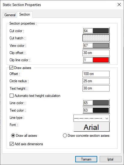
Section Tab
|
Specifications |
|
Cut colors Select the color of the cut objects from the color palette that appears when clicked. |
|
Cut hatch Select the hatch of cut objects by selecting one of the hatch options that open when clicked. |
|
View color Select the color of visible objects from the color palette that opens when clicked. |
|
Clip offset It is the value that determines the total height of the prepared section. The higher the value, the higher the height of the section plane. |
|
Clip line color It is the color of the line showing the cut of visible objects at the level where the section plane ends. Select the appropriate color from the color palette that opens when clicked. |
|
Draw axises It is the option that determines whether the axes that cut the section plane are shown in the section. When the option is selected, the axes are shown in section. |
|
Offset Indicates the remaining distance between the axis circles of the axes shown in the section and the section plane. The higher the value, the farther the axis circles are from the section. |
|
Circle radius The radius of the axis circles shown in the section. Axis circles surround the axis names. The larger the value, the larger the axis circles. |
|
Text height It is the text height of the axis names shown in the section. The higher the value, the larger the names are written. If the "automatic text height calculation" option just below is selected, the "text height" will be disabled and the axis text will be automatically fitted inside the axis circles. |
|
Automatic text height calculation If the "Automatic text height calculation" option is selected, the "Text height" value just above will be inactive and the axis text will automatically fit inside the axis circles. |
|
Line color The line color of the axis circles shown in the section. Select the appropriate color from the color palette that opens when the color box is clicked. |
|
Text color It is the font color of the axis texts shown in the section. Select the appropriate color from the color palette that opens when the color box is clicked. |
|
Line type It is the line type of the line drawn between axis circles and the section plane. Select the appropriate linetype from the list. |
|
Font The font of the axis texts shown in the section. Select the appropriate font from the font list that opens when the font box is clicked. |
|
Draw all axises When the option is checked, it shows all the axises defined during data entry, in their respective positions in the section. |
|
Draw concrete section axises When the option is checked, it shows the axises defined at the time of data entry but only intersecting the columns, in their positions in the section. |
|
Add axis dimensions If the option is selected, the spacing of the axises shown in the section is dimensioned. If not checked, it will not be dimensioned. |
Next Topic