
How does ideCAD calculate combined flexural and axial strength according to ACI 318-19?
-
Nominal flexural and axial strength are calculated automatically.
-
Nominal axial compressive strength is calculated automatically.
-
Nominal axial tensile strength is calculated automatically.
Download ideCAD for ACI 318-19
Notation
Ag = gross area of the concrete section, in2
As = area of non-prestressed longitudinal tension reinforcement, in2
Ast = total area of non-prestressed longitudinal reinforcement, in2
α = depth of equivalent rectangular stress block, in.
bw = width of compression face of the member, in.
c = distance from extreme compression fiber to the neutral axis, in.
Cc = concrete compressive force, lb
Cs = reinforcement tension force, lb
fc' = specified compressive strength of concrete, psi
fy = specified yield strength for non-prestressed reinforcement, psi
Mn = nominal flexural strength at section, in.-lb
Pn = nominal axial compressive strength of member, lb
Pn,max = maximum nominal axial compressive strength of a member, lb
Pnt = nominal axial tensile strength of member, lb
Pnt,max = maximum nominal axial tensile strength of member, lb
Po = nominal axial strength at zero eccentricity, lb
ϕ = strength reduction factor
εt = net tensile strain in the extreme layer of longitudinal tension reinforcement at nominal strength, excluding strains due to effective prestress, creep, shrinkage, and temperature
β1 = factor relating depth of equivalent rectangular compressive stress block to depth of neutral axis
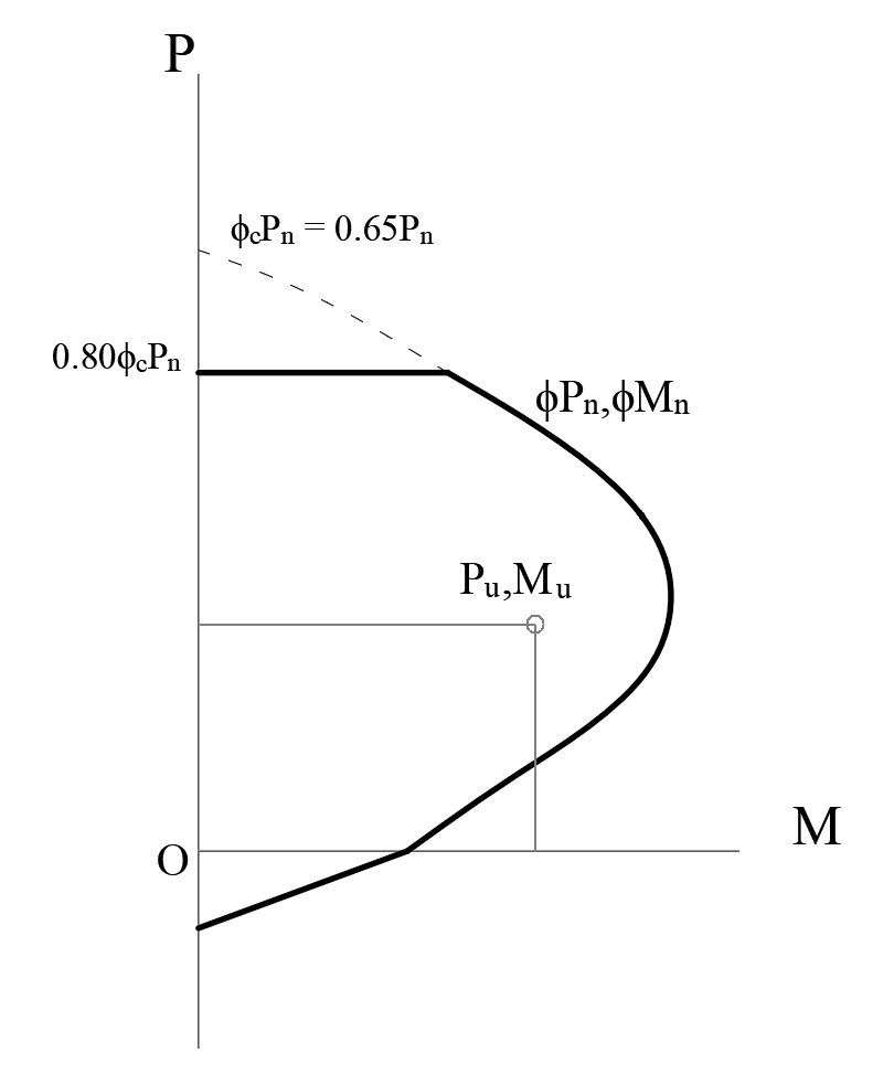
Maximum axial compressive strength
Nominal axial compressive strength Pn is limited to a value of Pn,max =0.8Po for non-prestressed members.
For non-prestressed concrete members, Po shall be calculated by:
'%3e%3cg transform='translate(167%2c0)'%3e%3cg transform='translate(-13%2c0)'%3e%3cg transform='translate(0%2c-3)'%3e%3cuse xlink:href='%23MJMATHI-50' x='0' y='0'%3e%3c/use%3e%3cuse transform='scale(0.707)' xlink:href='%23MJMATHI-6F' x='908' y='-213'%3e%3c/use%3e%3cuse xlink:href='%23MJMAIN-3D' x='1363' y='0'%3e%3c/use%3e%3cg transform='translate(2419%2c0)'%3e%3cuse xlink:href='%23MJMAIN-30'%3e%3c/use%3e%3cuse xlink:href='%23MJMAIN-2E' x='500' y='0'%3e%3c/use%3e%3cuse xlink:href='%23MJMAIN-38' x='779' y='0'%3e%3c/use%3e%3cuse xlink:href='%23MJMAIN-35' x='1279' y='0'%3e%3c/use%3e%3c/g%3e%3cg transform='translate(4199%2c0)'%3e%3cuse xlink:href='%23MJMATHI-66' x='0' y='0'%3e%3c/use%3e%3cuse transform='scale(0.707)' xlink:href='%23MJMAIN-2032' x='804' y='445'%3e%3c/use%3e%3cuse transform='scale(0.707)' xlink:href='%23MJMATHI-63' x='693' y='-211'%3e%3c/use%3e%3c/g%3e%3cuse xlink:href='%23MJMAIN-28' x='5096' y='0'%3e%3c/use%3e%3cg transform='translate(5486%2c0)'%3e%3cuse xlink:href='%23MJMATHI-41' x='0' y='0'%3e%3c/use%3e%3cuse transform='scale(0.707)' xlink:href='%23MJMATHI-67' x='1061' y='-213'%3e%3c/use%3e%3c/g%3e%3cuse xlink:href='%23MJMAIN-2212' x='6898' y='0'%3e%3c/use%3e%3cg transform='translate(7899%2c0)'%3e%3cuse xlink:href='%23MJMATHI-41' x='0' y='0'%3e%3c/use%3e%3cg transform='translate(750%2c-150)'%3e%3cuse transform='scale(0.707)' xlink:href='%23MJMATHI-73' x='0' y='0'%3e%3c/use%3e%3cuse transform='scale(0.707)' xlink:href='%23MJMATHI-74' x='469' y='0'%3e%3c/use%3e%3c/g%3e%3c/g%3e%3cuse xlink:href='%23MJMAIN-29' x='9337' y='0'%3e%3c/use%3e%3cuse xlink:href='%23MJMAIN-2B' x='9949' y='0'%3e%3c/use%3e%3cg transform='translate(10950%2c0)'%3e%3cuse xlink:href='%23MJMATHI-66' x='0' y='0'%3e%3c/use%3e%3cuse transform='scale(0.707)' xlink:href='%23MJMATHI-79' x='693' y='-213'%3e%3c/use%3e%3c/g%3e%3cg transform='translate(11892%2c0)'%3e%3cuse xlink:href='%23MJMATHI-41' x='0' y='0'%3e%3c/use%3e%3cg transform='translate(750%2c-150)'%3e%3cuse transform='scale(0.707)' xlink:href='%23MJMATHI-73' x='0' y='0'%3e%3c/use%3e%3cuse transform='scale(0.707)' xlink:href='%23MJMATHI-74' x='469' y='0'%3e%3c/use%3e%3c/g%3e%3c/g%3e%3c/g%3e%3c/g%3e%3c/g%3e%3c/g%3e%3c/svg%3e)
According to ACI Table 22.4.2.1 Maximum axial compressive strength for a non-prestressed concrete member with closed tie;
'%3e%3cg transform='translate(167%2c0)'%3e%3cg transform='translate(-13%2c0)'%3e%3cg transform='translate(0%2c-3)'%3e%3cuse xlink:href='%23MJMATHI-50' x='0' y='0'%3e%3c/use%3e%3cg transform='translate(642%2c-150)'%3e%3cuse transform='scale(0.707)' xlink:href='%23MJMATHI-6E' x='0' y='0'%3e%3c/use%3e%3cuse transform='scale(0.707)' xlink:href='%23MJMAIN-2C' x='600' y='0'%3e%3c/use%3e%3cuse transform='scale(0.707)' xlink:href='%23MJMATHI-6D' x='879' y='0'%3e%3c/use%3e%3cuse transform='scale(0.707)' xlink:href='%23MJMATHI-61' x='1757' y='0'%3e%3c/use%3e%3cuse transform='scale(0.707)' xlink:href='%23MJMATHI-78' x='2287' y='0'%3e%3c/use%3e%3c/g%3e%3cuse xlink:href='%23MJMAIN-3D' x='3042' y='0'%3e%3c/use%3e%3cg transform='translate(4098%2c0)'%3e%3cuse xlink:href='%23MJMAIN-30'%3e%3c/use%3e%3cuse xlink:href='%23MJMAIN-2E' x='500' y='0'%3e%3c/use%3e%3cuse xlink:href='%23MJMAIN-38' x='779' y='0'%3e%3c/use%3e%3cuse xlink:href='%23MJMAIN-30' x='1279' y='0'%3e%3c/use%3e%3c/g%3e%3cg transform='translate(5878%2c0)'%3e%3cuse xlink:href='%23MJMATHI-50' x='0' y='0'%3e%3c/use%3e%3cuse transform='scale(0.707)' xlink:href='%23MJMATHI-6F' x='908' y='-213'%3e%3c/use%3e%3c/g%3e%3cuse xlink:href='%23MJMAIN-3D' x='7242' y='0'%3e%3c/use%3e%3cg transform='translate(8298%2c0)'%3e%3cuse xlink:href='%23MJMAIN-30'%3e%3c/use%3e%3cuse xlink:href='%23MJMAIN-2E' x='500' y='0'%3e%3c/use%3e%3cuse xlink:href='%23MJMAIN-38' x='779' y='0'%3e%3c/use%3e%3cuse xlink:href='%23MJMAIN-30' x='1279' y='0'%3e%3c/use%3e%3c/g%3e%3cuse xlink:href='%23MJMAIN-D7' x='10300' y='0'%3e%3c/use%3e%3cg transform='translate(11301%2c0)'%3e%3cuse xlink:href='%23MJMAIN-30'%3e%3c/use%3e%3cuse xlink:href='%23MJMAIN-2E' x='500' y='0'%3e%3c/use%3e%3cuse xlink:href='%23MJMAIN-38' x='779' y='0'%3e%3c/use%3e%3cuse xlink:href='%23MJMAIN-35' x='1279' y='0'%3e%3c/use%3e%3c/g%3e%3cg transform='translate(13081%2c0)'%3e%3cuse xlink:href='%23MJMATHI-66' x='0' y='0'%3e%3c/use%3e%3cuse transform='scale(0.707)' xlink:href='%23MJMAIN-2032' x='804' y='445'%3e%3c/use%3e%3cuse transform='scale(0.707)' xlink:href='%23MJMATHI-63' x='693' y='-211'%3e%3c/use%3e%3c/g%3e%3cuse xlink:href='%23MJMAIN-28' x='13978' y='0'%3e%3c/use%3e%3cg transform='translate(14367%2c0)'%3e%3cuse xlink:href='%23MJMATHI-41' x='0' y='0'%3e%3c/use%3e%3cuse transform='scale(0.707)' xlink:href='%23MJMATHI-67' x='1061' y='-213'%3e%3c/use%3e%3c/g%3e%3cuse xlink:href='%23MJMAIN-2212' x='15780' y='0'%3e%3c/use%3e%3cg transform='translate(16781%2c0)'%3e%3cuse xlink:href='%23MJMATHI-41' x='0' y='0'%3e%3c/use%3e%3cg transform='translate(750%2c-150)'%3e%3cuse transform='scale(0.707)' xlink:href='%23MJMATHI-73' x='0' y='0'%3e%3c/use%3e%3cuse transform='scale(0.707)' xlink:href='%23MJMATHI-74' x='469' y='0'%3e%3c/use%3e%3c/g%3e%3c/g%3e%3cuse xlink:href='%23MJMAIN-29' x='18219' y='0'%3e%3c/use%3e%3cuse xlink:href='%23MJMAIN-2B' x='18830' y='0'%3e%3c/use%3e%3cg transform='translate(19831%2c0)'%3e%3cuse xlink:href='%23MJMATHI-66' x='0' y='0'%3e%3c/use%3e%3cuse transform='scale(0.707)' xlink:href='%23MJMATHI-79' x='693' y='-213'%3e%3c/use%3e%3c/g%3e%3cg transform='translate(20773%2c0)'%3e%3cuse xlink:href='%23MJMATHI-41' x='0' y='0'%3e%3c/use%3e%3cg transform='translate(750%2c-150)'%3e%3cuse transform='scale(0.707)' xlink:href='%23MJMATHI-73' x='0' y='0'%3e%3c/use%3e%3cuse transform='scale(0.707)' xlink:href='%23MJMATHI-74' x='469' y='0'%3e%3c/use%3e%3c/g%3e%3c/g%3e%3c/g%3e%3c/g%3e%3c/g%3e%3c/g%3e%3c/svg%3e)
The maximum design compressive strength for a non-prestressed concrete member with a closed tie;
'%3e%3cg transform='translate(167%2c0)'%3e%3cg transform='translate(-13%2c0)'%3e%3cg transform='translate(0%2c-6)'%3e%3cuse xlink:href='%23MJMATHI-3D5' x='0' y='0'%3e%3c/use%3e%3cg transform='translate(596%2c0)'%3e%3cuse xlink:href='%23MJMATHI-50' x='0' y='0'%3e%3c/use%3e%3cg transform='translate(642%2c-150)'%3e%3cuse transform='scale(0.707)' xlink:href='%23MJMATHI-6E' x='0' y='0'%3e%3c/use%3e%3cuse transform='scale(0.707)' xlink:href='%23MJMAIN-2C' x='600' y='0'%3e%3c/use%3e%3cuse transform='scale(0.707)' xlink:href='%23MJMATHI-6D' x='879' y='0'%3e%3c/use%3e%3cuse transform='scale(0.707)' xlink:href='%23MJMATHI-61' x='1757' y='0'%3e%3c/use%3e%3cuse transform='scale(0.707)' xlink:href='%23MJMATHI-78' x='2287' y='0'%3e%3c/use%3e%3c/g%3e%3c/g%3e%3cuse xlink:href='%23MJMAIN-3D' x='3638' y='0'%3e%3c/use%3e%3cuse xlink:href='%23MJMATHI-3D5' x='4695' y='0'%3e%3c/use%3e%3cg transform='translate(5291%2c0)'%3e%3cuse xlink:href='%23MJMAIN-30'%3e%3c/use%3e%3cuse xlink:href='%23MJMAIN-2E' x='500' y='0'%3e%3c/use%3e%3cuse xlink:href='%23MJMAIN-38' x='779' y='0'%3e%3c/use%3e%3cuse xlink:href='%23MJMAIN-30' x='1279' y='0'%3e%3c/use%3e%3c/g%3e%3cg transform='translate(7071%2c0)'%3e%3cuse xlink:href='%23MJMATHI-50' x='0' y='0'%3e%3c/use%3e%3cuse transform='scale(0.707)' xlink:href='%23MJMATHI-6F' x='908' y='-213'%3e%3c/use%3e%3c/g%3e%3c/g%3e%3c/g%3e%3c/g%3e%3c/g%3e%3c/svg%3e)
Strength reduction factors ϕ is determined according to using ACI Table 21.2.2. Since the section is compression controlled, a ϕ factor for compression control is used.
Maximum axial tensile strength
Nominal axial tensile strength Pnt is limited to a value of Pnt,max in ACI 22.4.3.1.
'%3e%3cg transform='translate(167%2c0)'%3e%3cg transform='translate(-13%2c0)'%3e%3cg transform='translate(0%2c-3)'%3e%3cuse xlink:href='%23MJMATHI-50' x='0' y='0'%3e%3c/use%3e%3cg transform='translate(642%2c-150)'%3e%3cuse transform='scale(0.707)' xlink:href='%23MJMATHI-6E' x='0' y='0'%3e%3c/use%3e%3cuse transform='scale(0.707)' xlink:href='%23MJMATHI-74' x='600' y='0'%3e%3c/use%3e%3cuse transform='scale(0.707)' xlink:href='%23MJMAIN-2C' x='962' y='0'%3e%3c/use%3e%3cuse transform='scale(0.707)' xlink:href='%23MJMATHI-6D' x='1240' y='0'%3e%3c/use%3e%3cuse transform='scale(0.707)' xlink:href='%23MJMATHI-61' x='2119' y='0'%3e%3c/use%3e%3cuse transform='scale(0.707)' xlink:href='%23MJMATHI-78' x='2648' y='0'%3e%3c/use%3e%3c/g%3e%3cuse xlink:href='%23MJMAIN-3D' x='3297' y='0'%3e%3c/use%3e%3cg transform='translate(4354%2c0)'%3e%3cuse xlink:href='%23MJMATHI-66' x='0' y='0'%3e%3c/use%3e%3cuse transform='scale(0.707)' xlink:href='%23MJMATHI-79' x='693' y='-213'%3e%3c/use%3e%3c/g%3e%3cuse xlink:href='%23MJMAIN-28' x='5296' y='0'%3e%3c/use%3e%3cg transform='translate(5685%2c0)'%3e%3cuse xlink:href='%23MJMATHI-41' x='0' y='0'%3e%3c/use%3e%3cg transform='translate(750%2c-150)'%3e%3cuse transform='scale(0.707)' xlink:href='%23MJMATHI-73' x='0' y='0'%3e%3c/use%3e%3cuse transform='scale(0.707)' xlink:href='%23MJMATHI-74' x='469' y='0'%3e%3c/use%3e%3c/g%3e%3c/g%3e%3cuse xlink:href='%23MJMAIN-29' x='7124' y='0'%3e%3c/use%3e%3c/g%3e%3c/g%3e%3c/g%3e%3c/g%3e%3c/svg%3e)
The maximum tensile axial load for a non-prestressed concrete member;
'%3e%3cg transform='translate(167%2c0)'%3e%3cg transform='translate(-13%2c0)'%3e%3cg transform='translate(0%2c-3)'%3e%3cuse xlink:href='%23MJMATHI-3D5' x='0' y='0'%3e%3c/use%3e%3cg transform='translate(596%2c0)'%3e%3cuse xlink:href='%23MJMATHI-50' x='0' y='0'%3e%3c/use%3e%3cg transform='translate(642%2c-150)'%3e%3cuse transform='scale(0.707)' xlink:href='%23MJMATHI-6E' x='0' y='0'%3e%3c/use%3e%3cuse transform='scale(0.707)' xlink:href='%23MJMATHI-74' x='600' y='0'%3e%3c/use%3e%3cuse transform='scale(0.707)' xlink:href='%23MJMAIN-2C' x='962' y='0'%3e%3c/use%3e%3cuse transform='scale(0.707)' xlink:href='%23MJMATHI-6D' x='1240' y='0'%3e%3c/use%3e%3cuse transform='scale(0.707)' xlink:href='%23MJMATHI-61' x='2119' y='0'%3e%3c/use%3e%3cuse transform='scale(0.707)' xlink:href='%23MJMATHI-78' x='2648' y='0'%3e%3c/use%3e%3c/g%3e%3c/g%3e%3cuse xlink:href='%23MJMAIN-3D' x='3894' y='0'%3e%3c/use%3e%3cuse xlink:href='%23MJMATHI-3D5' x='4950' y='0'%3e%3c/use%3e%3cg transform='translate(5547%2c0)'%3e%3cuse xlink:href='%23MJMATHI-66' x='0' y='0'%3e%3c/use%3e%3cuse transform='scale(0.707)' xlink:href='%23MJMATHI-79' x='693' y='-213'%3e%3c/use%3e%3c/g%3e%3cuse xlink:href='%23MJMAIN-28' x='6489' y='0'%3e%3c/use%3e%3cg transform='translate(6878%2c0)'%3e%3cuse xlink:href='%23MJMATHI-41' x='0' y='0'%3e%3c/use%3e%3cg transform='translate(750%2c-150)'%3e%3cuse transform='scale(0.707)' xlink:href='%23MJMATHI-73' x='0' y='0'%3e%3c/use%3e%3cuse transform='scale(0.707)' xlink:href='%23MJMATHI-74' x='469' y='0'%3e%3c/use%3e%3c/g%3e%3c/g%3e%3cuse xlink:href='%23MJMAIN-29' x='8317' y='0'%3e%3c/use%3e%3c/g%3e%3c/g%3e%3c/g%3e%3c/g%3e%3c/svg%3e)
Strength reduction factors ϕ is determined according to using ACI Table 21.2.2. Since the section is tension controlled, a ϕ factor for tension control is used.
|
Strain, εt |
Section Classification |
ϕ |
|---|---|---|
|
εt ≤ εty |
Compression Controlled Moment |
0.65 |
|
εty < εt < (εty + 0.003) |
Transition region |
0.65 + 0.25[(εt - εty)/0.003] |
|
εt ≥ (εty + 0.003) |
Compression Controlled Moment |
0.90 |
Design assumptions
The flexural and axial strength of a member calculated by the strength design method, two basic conditions should be satisfied:
-
equilibrium
-
compatibility of strains
Equilibrium means balancing of forces acting on the element cross section at nominal strength. Stress-strain relationship for the concrete and the reinforcement at nominal strength is established within the design assumptions described following:
-
Equilibrium is satisfied in each section.
-
It is assumed that strain in concrete and reinforcement is proportional to the distance from the neutral axis.
Design strength is calculated by using these assumptions together with design assumptions for concrete described following:
-
Maximum strain at the extreme concrete compression fiber is assumed to equal 0.003.
-
The tensile strength of concrete is neglected.
-
The equivalent rectangular concrete stress distribution method represents the relationship between concrete compressive stress and strain.
-
Concrete stress of 0.85fc' is assumed to be uniformly distributed over. Equivalent rectangular concrete stress zone bounded by edges of the cross-section and a line parallel to the neutral axis located a distance α from the fiber of maximum compressive strain, as calculated by:
'%3e%3cg transform='translate(167%2c0)'%3e%3cg transform='translate(-13%2c0)'%3e%3cg transform='translate(0%2c-50)'%3e%3cuse xlink:href='%23MJMATHI-3B1' x='0' y='0'%3e%3c/use%3e%3cuse xlink:href='%23MJMAIN-3D' x='918' y='0'%3e%3c/use%3e%3cg transform='translate(1974%2c0)'%3e%3cuse xlink:href='%23MJMATHI-3B2' x='0' y='0'%3e%3c/use%3e%3cuse transform='scale(0.707)' xlink:href='%23MJMAIN-31' x='801' y='-213'%3e%3c/use%3e%3c/g%3e%3cuse xlink:href='%23MJMATHI-63' x='2994' y='0'%3e%3c/use%3e%3c/g%3e%3c/g%3e%3c/g%3e%3c/g%3e%3c/svg%3e)
-
The distance between the fiber of maximum compressive stress and the neutral axis, c, is perpendicular to the neutral axis.
-
The value of β1 is determined using ACI Table 22.2.2.4.3.
|
fc' , psi |
β1 |
|---|---|
|
2500 ≤ fc' ≤ 4000 |
0.85 |
|
4000 < fc' < 8000 |
0.85 - 0.05(fc' -4000)/1000 |
|
fc' ≥ 8000 |
0.65 |
Combined Flexural and Axial Strength
Nominal flexural strength Mn and axial strength are calculated using Design Assumptions. While finding the flexural design strength, combined with axial force ϕMn, it should be found in which control zone the cross-section is. When the section is tension controlled, a ϕ factor for tension control is used. A ϕ factor for compression control is used when the section is compression controlled. When the section is within the transition region, ϕ is linearly interpolated between the two limit values.
Nominal flexural strength Mn with zero compression is calculated as described in the title of Flexural Strength per ACI 318-19 with ideCAD. Similarly, with the same design assumptions combined nominal flexural and axial strength Mn and Pn are calculated as shown below.
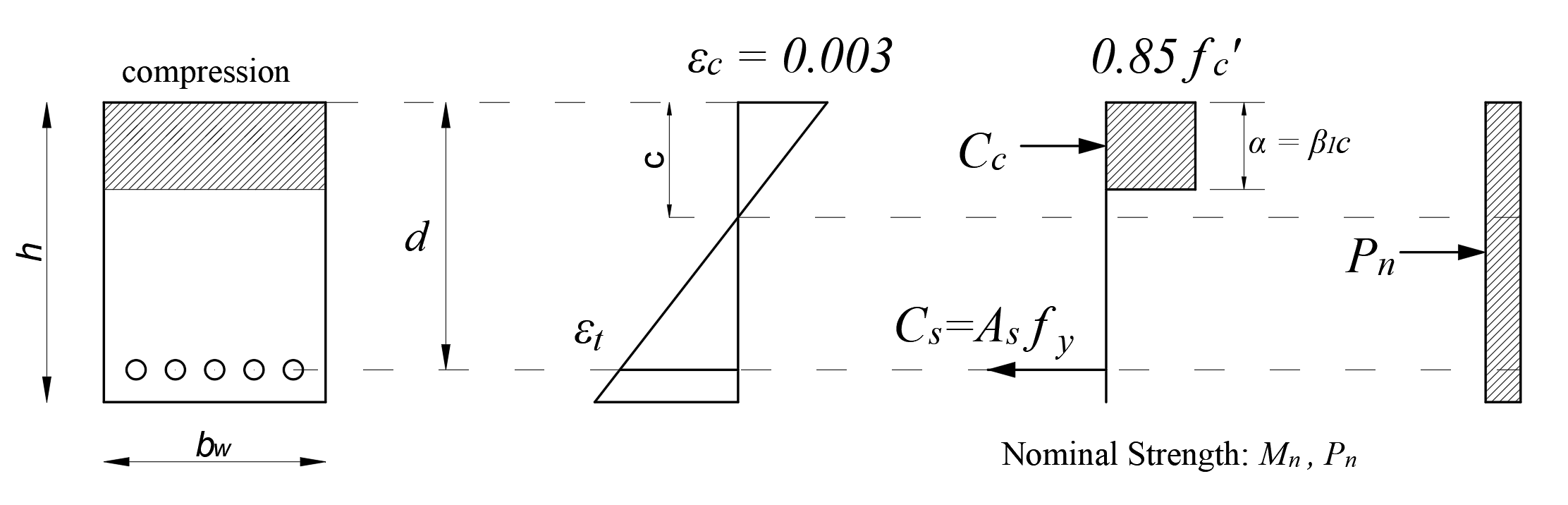
From the equation of equilibrium:
'%3e%3cg transform='translate(167%2c0)'%3e%3cg transform='translate(-13%2c0)'%3e%3cg transform='translate(0%2c-50)'%3e%3cuse xlink:href='%23MJMATHI-50' x='0' y='0'%3e%3c/use%3e%3cuse transform='scale(0.707)' xlink:href='%23MJMATHI-6E' x='908' y='-213'%3e%3c/use%3e%3cuse xlink:href='%23MJMAIN-3D' x='1444' y='0'%3e%3c/use%3e%3cg transform='translate(2501%2c0)'%3e%3cuse xlink:href='%23MJMATHI-43' x='0' y='0'%3e%3c/use%3e%3cuse transform='scale(0.707)' xlink:href='%23MJMATHI-73' x='1011' y='-213'%3e%3c/use%3e%3c/g%3e%3cuse xlink:href='%23MJMAIN-2212' x='3870' y='0'%3e%3c/use%3e%3cg transform='translate(4871%2c0)'%3e%3cuse xlink:href='%23MJMATHI-43' x='0' y='0'%3e%3c/use%3e%3cuse transform='scale(0.707)' xlink:href='%23MJMATHI-63' x='1011' y='-213'%3e%3c/use%3e%3c/g%3e%3c/g%3e%3c/g%3e%3c/g%3e%3c/g%3e%3c/svg%3e)
Nominal flexural strength Mn:
'%3e%3cg transform='translate(167%2c0)'%3e%3cg transform='translate(-13%2c0)'%3e%3cuse xlink:href='%23MJMATHI-4D' x='0' y='0'%3e%3c/use%3e%3cuse transform='scale(0.707)' xlink:href='%23MJMATHI-6E' x='1372' y='-213'%3e%3c/use%3e%3cuse xlink:href='%23MJMAIN-3D' x='1772' y='0'%3e%3c/use%3e%3cg transform='translate(2829%2c0)'%3e%3cuse xlink:href='%23MJMAIN-30'%3e%3c/use%3e%3cuse xlink:href='%23MJMAIN-2E' x='500' y='0'%3e%3c/use%3e%3cuse xlink:href='%23MJMAIN-38' x='779' y='0'%3e%3c/use%3e%3cuse xlink:href='%23MJMAIN-35' x='1279' y='0'%3e%3c/use%3e%3c/g%3e%3cg transform='translate(4609%2c0)'%3e%3cuse xlink:href='%23MJMATHI-66' x='0' y='0'%3e%3c/use%3e%3cuse transform='scale(0.707)' xlink:href='%23MJMAIN-2032' x='804' y='445'%3e%3c/use%3e%3cuse transform='scale(0.707)' xlink:href='%23MJMATHI-63' x='693' y='-211'%3e%3c/use%3e%3c/g%3e%3cuse xlink:href='%23MJMAIN-28' x='5506' y='0'%3e%3c/use%3e%3cg transform='translate(5895%2c0)'%3e%3cuse xlink:href='%23MJMATHI-62' x='0' y='0'%3e%3c/use%3e%3cuse transform='scale(0.707)' xlink:href='%23MJMATHI-77' x='607' y='-213'%3e%3c/use%3e%3c/g%3e%3cuse xlink:href='%23MJMATHI-3B1' x='6931' y='0'%3e%3c/use%3e%3cuse xlink:href='%23MJMAIN-29' x='7572' y='0'%3e%3c/use%3e%3cuse xlink:href='%23MJMAIN-D7' x='8184' y='0'%3e%3c/use%3e%3cuse xlink:href='%23MJMAIN-28' x='9184' y='0'%3e%3c/use%3e%3cuse xlink:href='%23MJMATHI-64' x='9574' y='0'%3e%3c/use%3e%3cuse xlink:href='%23MJMAIN-2212' x='10320' y='0'%3e%3c/use%3e%3cg transform='translate(11098%2c0)'%3e%3cg transform='translate(342%2c0)'%3e%3crect stroke='none' width='572' height='60' x='0' y='220'%3e%3c/rect%3e%3cuse transform='scale(0.707)' xlink:href='%23MJMATHI-3B1' x='84' y='613'%3e%3c/use%3e%3cuse transform='scale(0.707)' xlink:href='%23MJMAIN-32' x='154' y='-562'%3e%3c/use%3e%3c/g%3e%3c/g%3e%3cuse xlink:href='%23MJMAIN-29' x='12133' y='0'%3e%3c/use%3e%3cuse xlink:href='%23MJMAIN-2B' x='12745' y='0'%3e%3c/use%3e%3cg transform='translate(13746%2c0)'%3e%3cuse xlink:href='%23MJMATHI-50' x='0' y='0'%3e%3c/use%3e%3cuse transform='scale(0.707)' xlink:href='%23MJMATHI-6E' x='908' y='-213'%3e%3c/use%3e%3c/g%3e%3cuse xlink:href='%23MJMAIN-D7' x='15135' y='0'%3e%3c/use%3e%3cuse xlink:href='%23MJSZ2-28' x='16136' y='-1'%3e%3c/use%3e%3cg transform='translate(16733%2c0)'%3e%3cg transform='translate(120%2c0)'%3e%3crect stroke='none' width='527' height='60' x='0' y='220'%3e%3c/rect%3e%3cuse transform='scale(0.707)' xlink:href='%23MJMATHI-68' x='84' y='613'%3e%3c/use%3e%3cuse transform='scale(0.707)' xlink:href='%23MJMAIN-32' x='122' y='-562'%3e%3c/use%3e%3c/g%3e%3c/g%3e%3cuse xlink:href='%23MJMAIN-2212' x='17723' y='0'%3e%3c/use%3e%3cuse xlink:href='%23MJMAIN-28' x='18724' y='0'%3e%3c/use%3e%3cuse xlink:href='%23MJMATHI-68' x='19113' y='0'%3e%3c/use%3e%3cuse xlink:href='%23MJMAIN-2212' x='19912' y='0'%3e%3c/use%3e%3cuse xlink:href='%23MJMATHI-64' x='20913' y='0'%3e%3c/use%3e%3cuse xlink:href='%23MJMAIN-29' x='21436' y='0'%3e%3c/use%3e%3cuse xlink:href='%23MJSZ2-29' x='21826' y='-1'%3e%3c/use%3e%3c/g%3e%3c/g%3e%3c/g%3e%3c/svg%3e)