15.7.1.1
The unit deformation demands of concrete and reinforcement steel are compared with limit values and the performance of the carrier system at the cross-sectional level is determined automatically.
ICONS
c = neutral axis height
L p = plastic hinge length
M y = effective yield moment
M u = collapse moment
ϕ = curvature
ϕ y = yield curvature
ϕ u = curvature before crushing
ϕ t = total curvature demand
ε c = concrete pressure unit deformation
ε s = Reinforcement strain
θ y = Yield rotation
θk = displaced axis rotation
θ ki = displaced axis rotation at end i
In determining the earthquake performance of existing buildings with the Assessment and Design Based on Shaping (ŞGDT) approach, linear calculation methods or nonlinear calculation method and earthquake calculation are used. When the linear earthquake calculation is applied, the unit deformation demands obtained in TBDY Section 15.5.4 or when the non-linear earthquake calculation is applied , the unit deformation demands obtained according to the TBDY Section 15.6.2 are compared with the unit deformation capacities and the load-bearing system performance at the cross-section level is determined.
Evaluation of existing buildings and design according to Strain (ŞGDT) determining the seismic performance of the linear approximation calculation method is applied lead member end curvature φ t , Eq. (2.15), wherein the correlation is calculated. The detailed explanation has been made at 15.5.4.2 .

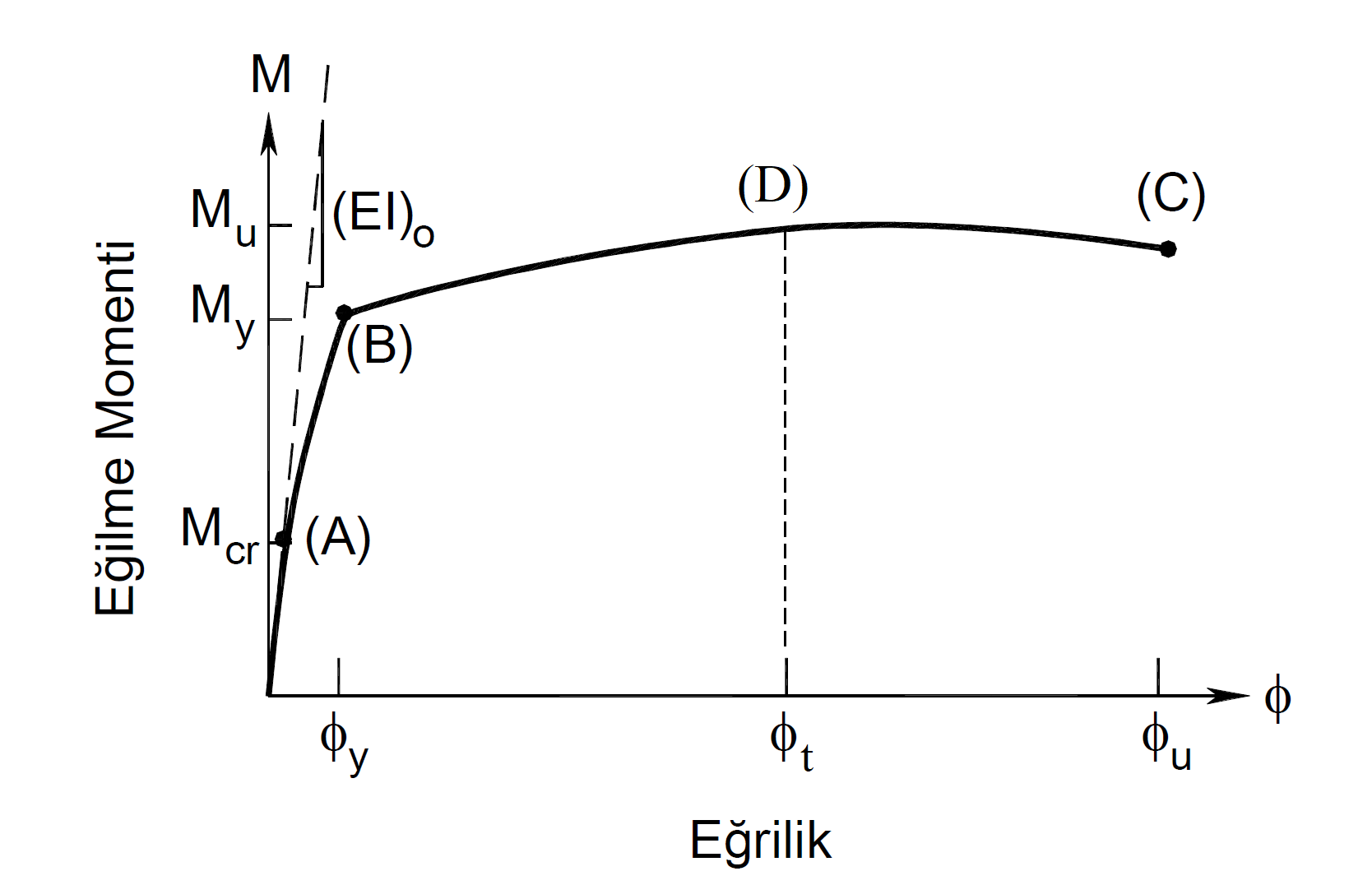
After calculating the element end curvature demand ϕ t , the unit deformation demands can be calculated in all unwound and unwound concrete and reinforcement fibers (fiber) in the section. The figure below shows a sample moment curvature plot. In this graph, point (B) is the point where the reinforcement reaches the yield stress. Moment value at point (B) found as a result of the moment-curvature analysis is named as flow moment M y , and curvature is named as flow curvature ϕ y . After this point, plastic deformations occur in the cross section. Point (C) is the failure point of the section and the moment at this point is the failure moment or moment capacity M u , and the curvature is the pre-collapse curvature ϕ u.is called. After this point, the cross section loses its load carrying capacity and plastic deformation capability and collapses. When the linear calculation method is applied in the performance analysis, since there is no plastic joint definition, these values are reached with Equation (15.2) . Therefore, moment-curvature analysis should be used indirectly. The element end curvature demand ϕ t , found by Equation (15.2) , is replaced in the moment curvature graph, and the material unit deformation values at this point are obtained. The curvature demand in the moment curvature graph is shown as point (D).

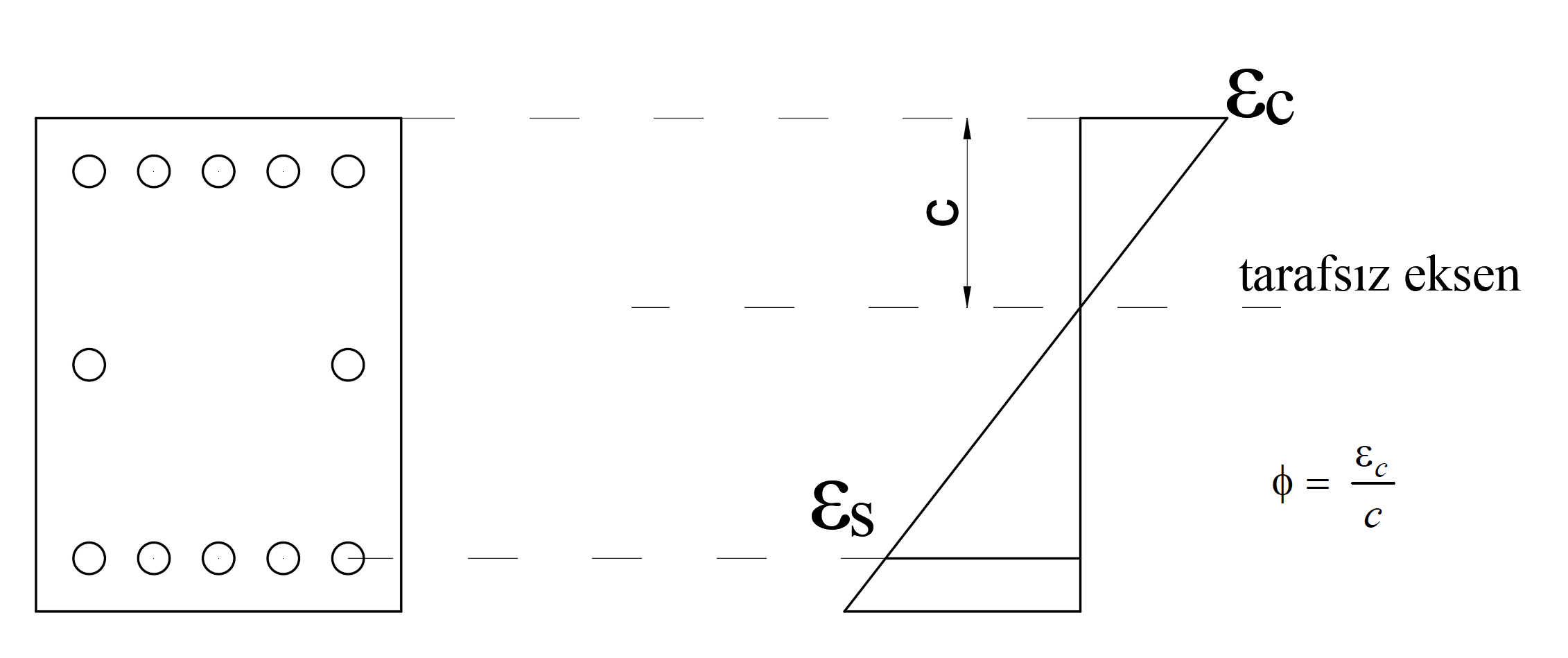
The relationship between the curvature value at any point and the cross-section deformation is shown in the figure below.

In the above equation, the highest point of the volume element in the fiber cross-sectional deformation value ε c and c are shown as neutral axis height. The curvature value is expressed as ϕ = ε c / c. In this case, the curvature demand ϕ is the concrete unit deformation value ε c and the reinforcement unit deformation value ε s on the curve t is the unit deformation demands of the concrete and reinforcement.
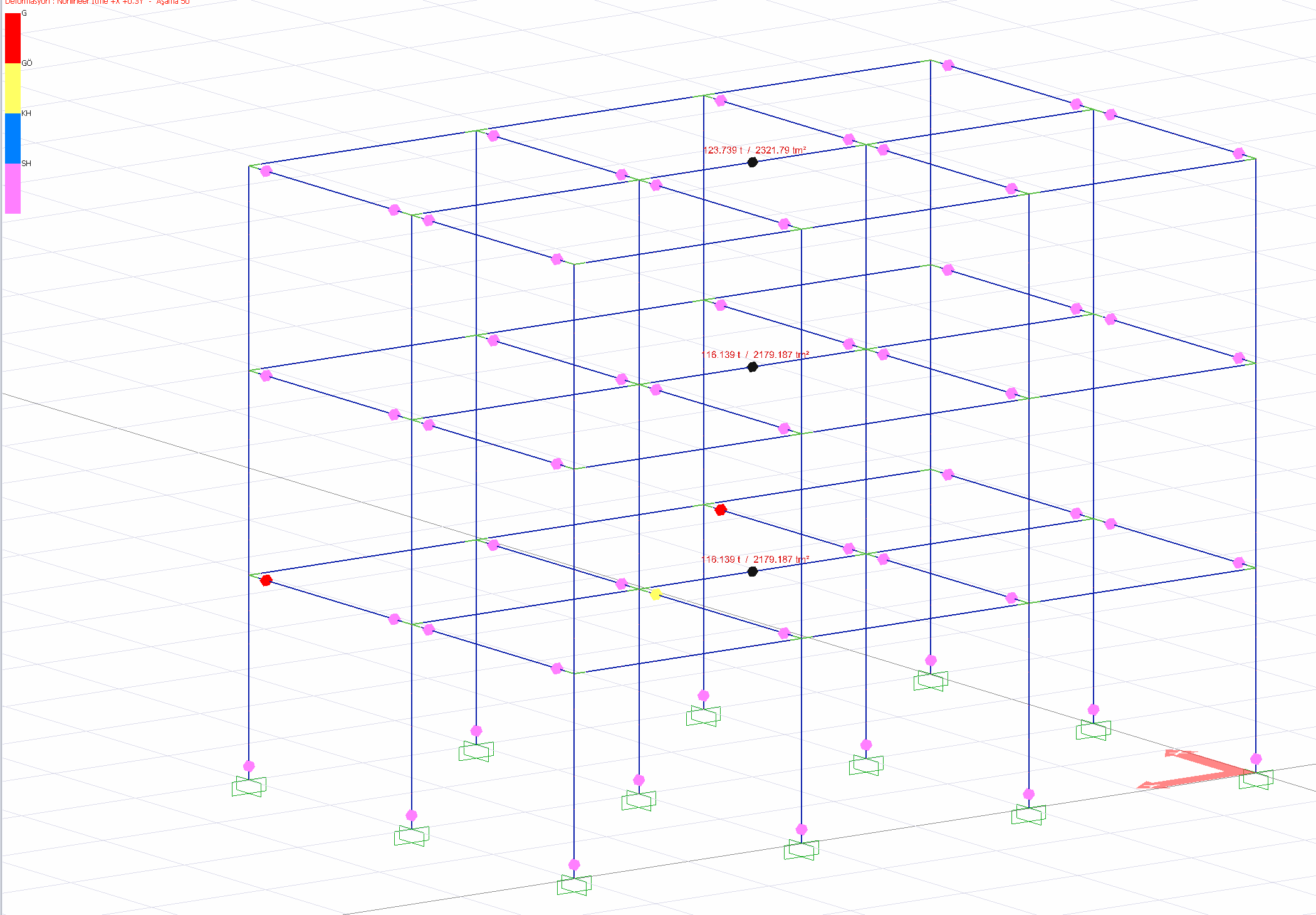
When the nonlinear calculation method is applied to determine the earthquake performance of existing buildings with the Assessment and Design Based on Shaping (ŞGDT) approach, the plastic hinge rotation values according to the piled plastic behavior model are compared with the plastic rotation limit values calculated in accordance with the performance analysis of the existing buildings . Plastic joint rotation values are calculated as a result of the thrust analysis and the cross section performance is determined by comparing with limit values.

Next Topic
Related Topics
