
How does ideCAD design End Plate Moment Connections according to AISC 358-16 & AISC 360-16?
-
Limit states of end plate moment connections are calculated automatically according to AISC 358-16 and AISC 360-16.
Symbols
bbf = width of beam flange, in. (mm)
bp = width of end-plate, in. (mm)
d = depth of connecting beam, in. (mm)
g = horizontal distance between bolts, in. (mm)
pb = vertical distance between the inner and outer row of bolts in an eight-bolt stiffened connection, in. (mm)
pfi = vertical distance from the inside of a beam tension flange to the nearest inside bolt row, in. (mm)
pfo = vertical distance from the outside of a beam tension flange to the nearest outside bolt row, in. (mm)
tbf = thickness of beam flange, in. (mm)
tp = thickness of end-plate, in. (mm)
Bolted Stiffened and Unstiffened End Plate Connections
End-plate connections consist of welding the beam to an end-plate and bolting the end-plate to a column flange.
If there is no axial load on the connection, total tensile and compressive forces are equal and opposite in both flanges, so that total force creates a force pair. It is accepted that the center of rotation is in the center of the compression flange.
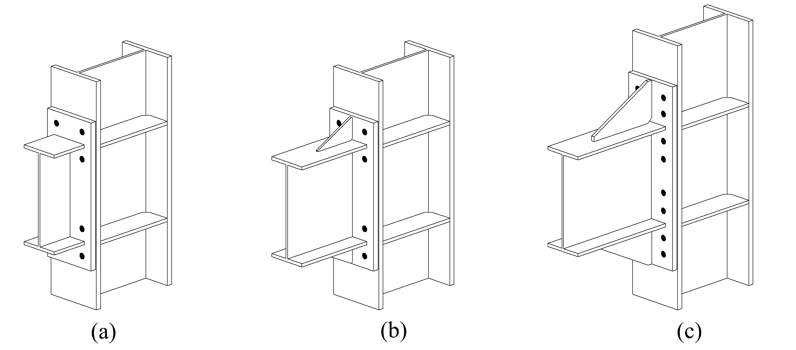
Extended end-plate moment connections are prequalified in special moment frame (SMF) and intermediate moment frame (IMF) systems. Configurations of extended end-plate moment connections are given below.
-
Four Bolts Unstiffened End Plate Connection (a)
-
Four Bolts Stiffened End Plate Connection (b)
-
Eight Bolts Stiffened End Plate Connection (c)
The limit states of end-plate moment connections are listed below.
-
Flexural yielding of the beam section
-
Flexural yielding of the end plates
-
Yielding of the column panel zone
-
Tension rupture of the end-plate bolts
-
Shear rupture of the end-plate bolts
-
Rupture of various welded joints.
The limit state checks listed above are applied automatically, and detailed explanations, references, and parameters used in the account are given in the connection report.
There are prequalification limits for moment connections that have been satisfactorily tested. All end-plate moment connection configurations should satisfy these beam and column limitations. Beam and column limitations are given in AISC 358-16 6.3. ideCAD Structural automatically checks Beam and column limitations.
|
Parametric Limitations on Prequalification |
||||||
|---|---|---|---|---|---|---|
|
|
Four-Bolt Unstiffened |
Four-Bolt Stiffened |
Eight-Bolt Stiffened |
|||
|
Parameter |
Maximum
|
Minimum
|
Maximum
|
Minimum
|
Maximum
|
Minimum
|
|
tbf |
3/4 (19) |
3/8 (10) |
3/4 (19) |
3/8 (10) |
1 (25) |
9/16 (14) |
|
bbf |
91/4 (235) |
6 (152) |
9 (229) |
6 (152) |
121/4 (311) |
71/2 (190) |
|
d |
55 (1400) |
133/4 (349) |
24 (610) |
133/4 (349) |
36 (914) |
18 (547) |
|
tp |
21/4 (57) |
1/2 (13) |
11/2 (38) |
1/2 (13) |
21/2 (64) |
3/4 (19) |
|
bp |
103/4 (273) |
7 (178) |
103/4 (273) |
7 (178) |
15 (381) |
9 (229) |
|
g |
6 (152) |
4 (102) |
6 (152) |
31/4 (83) |
6 (152) |
5 (127) |
|
pfi , pfo |
41/4 (114) |
11/2 (38) |
51/2 (140) |
13/4 (44) |
2 (51) |
15/8 (41) |
|
pb |
- |
- |
- |
- |
33/4 (95) |
31/2 (89) |
Plastic hinges cause inelastic bending deformations in the joining beam and column panel zones. Therefore, panel zones should conform to the requirements of the AISC Seismic Provisions. In addition, Column-beam moment ratios should conform to the requirements of the AISC Seismic Provisions.
Also, it should be checked that:
-
The clear span-to-depth ratio of the beam is limited:
-
For SMF systems, seven or greater.
-
For IMF systems, five or greater.
-
-
The protected zone is determined:
-
For unstiffened extended end-plate connections: the portion of the beam between the face of the column and a distance equal to the depth of the beam or three times the width of the beam flange from the face of the column, whichever is less.
-
For stiffened extended end-plate connections: the portion of the beam between the face of the column and a distance equal to the location of the end of the stiffener plus one-half the depth of the beam or three times the width of the beam flange, whichever is less.
-
-
The end plate should be connected to the flange of the column.
-
The rolled-shape column depth is limited to 36 in. (920 mm.) maximum. The depth of built-up wide-flange columns does not exceed that for rolled shapes.
End Plate Connections Design Steps
-
The strength of the end plate moment connection is determined by the assumption that the rupture limit state controls the tensile force of the bolts in one flange under compressive force.
-
If there is no axial load on the joint, the total tensile and compressive forces are equal and opposite in both flanges so that the total force creates a force pair.
-
The flexural strength of the end plate and column flange is determined by yield line analysis. The yield line mechanism is calculated by the energy or virtual work method.
-
A strong column, strong joint, and weak beam are used to calculate the forces on the bolt and find the required bolt strength. According to this assumption, while the column, panel zones, and beam have inelastic deformation, the connection and column have elastic behavior. For this reason, it is necessary to design a suitable thickness for the end plate.
-
The equations used are as follows:
-