
Analysis, design and code requirements check results of ribbed or waffle slabs are displayed in the Ribbed-Waffle Reinforcements dialogue. Reinforcement and internal force (moment, shear force) information on rib and waffle beams are given in the Ribbed-Waffle Reinforcements dialog.
Location of Ribbed - Waffle Slab Reinforcements Dialogue
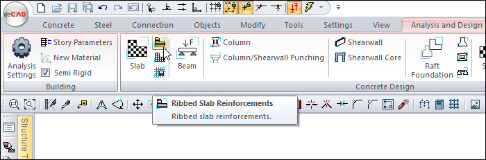
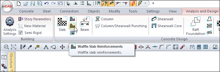
After analysis, you can access it by clicking on the Ribbed/Waffle Reinforcements command under the Concrete Design title of the ribbon menu Analysis and Design tab .
General Specifications of Ribbed-Waffle Reinforcements Dialogue
|
Summary Information The summary information about the line where the cursor is located is given in the form of Story, Name, and Position in the name of the dialog. 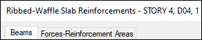
For example, Story 4, D04, 1 |
|
Using the Shift key In this tab, you can select more than one row with the Shift key, enter a value by double-clicking any cell whose value is open to change, and make that value apply to all selected rows. |
|
Using the Ctrl key Ctrl key, on the other hand, selects the lines in between one by one. |
|
Show horizontals By selecting the option, teeth are made in Horizontals (X) directions in the ribbed - waffle slab reinforcements design dialog. |
|
Show verticals By selecting the option, teeth are made in Verticals (Y) directions in the ribbed - waffle slab reinforcements design dialog. |
|
Reinforcement calculator Calculates the amount of rebar, in area, for the selected diameter and span. |
|
Previous The cursor moves to the previous line. |
|
Next The cursor goes to the next line. |
|
Ok It saves the changes made and closes the dialog. |
|
Cancel Closes the dialog without saving the changes made. |
Insufficiency Code Description and Recommended Solution
|
Insufficiency Code |
Description and Recommended Solution |
|---|---|
|
M |
The maximum reinforcement ratio is exceeded.
|
|
S |
According to the design code, serviceability (instantaneous and long-term deflection) limits are unmet.
|
|
Min |
The rib cross-section does not satisfy the design code’s minimum dimension requirements.
|
|
As(–) |
Provided reinforcement area is insufficient; an adequately large bar diameter may not have been selected.
|
|
h |
Rib depth is below the minimum height specified in the design code. Recommended action: Increase rib depth to meet the minimum height requirement. |
|
e |
Center-to-center rib spacing exceeds the maximum allowed (700 mm) per the design code.
|
|
bw |
The rib width is less than the minimum 100 mm required by the design code.
|
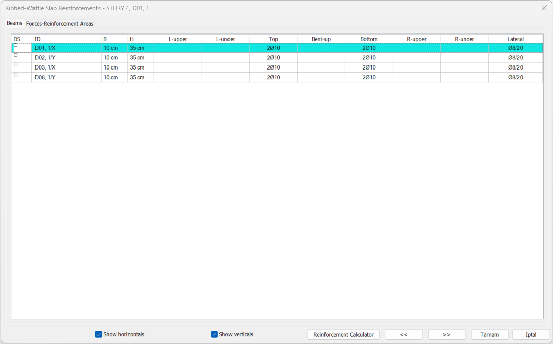
Beams Tab
In this tab, the list of ribbed/waffle dimensions and rebar is given as a table.
|
Specifications |
|---|
|
DS It is the rebar fixing column. If marked, the rebar is fixed. When changes are made in the rebar , DS is marked automatically and when the re-calculation is made, the rebar remains constant. |
|
ID 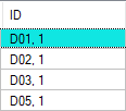
It is the name of the beam in the plan. (D1, D101, D10 etc.) In case of negativity, the term related to negativity is added next to the name. Like D101 (M) ... Each tile is listed by typical number of beam. |
|
B, H 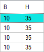
Beam is the width and height of the tooth, respectively. You can change the dimensions by double clicking in the B and H cells. When the size is changed, the dental rebar calculation is made for that beam according to the changed dimensions. |
|
L-upper 
It is the value in terms of number and diameter of the rebar located on the left support section of the beam. You can make changes by double-clicking the cell. |
|
L-under 
It is the value of the rebar under the left support section of the beam in terms of number and diameter. You can make changes by double-clicking the cell. |
|
Top 
It is the value of the mounting rebar of the thread in terms of number and diameter. You can make changes by double-clicking the cell. |
|
Bent-up 
It is the value of the pleated rebar of the thread in terms of number and diameter. You can make changes by double-clicking the cell. |
|
Bottom 
It is the value of the straight rebar of the thread in terms of number and diameter. You can make changes by double-clicking the cell. |
|
R-upper 
It is the value in terms of number and diameter of the rebar located on the right support section of the beam. You can make changes by double-clicking the cell. |
|
R-under 
It is the value of the rebar under the right support section of the beam in terms of number and diameter. You can make changes by double-clicking the cell. |
|
Lateral 
It is the diameter and range of the gingiva in the middle zone and densification zone, respectively. You can make changes by double-clicking the cell. |
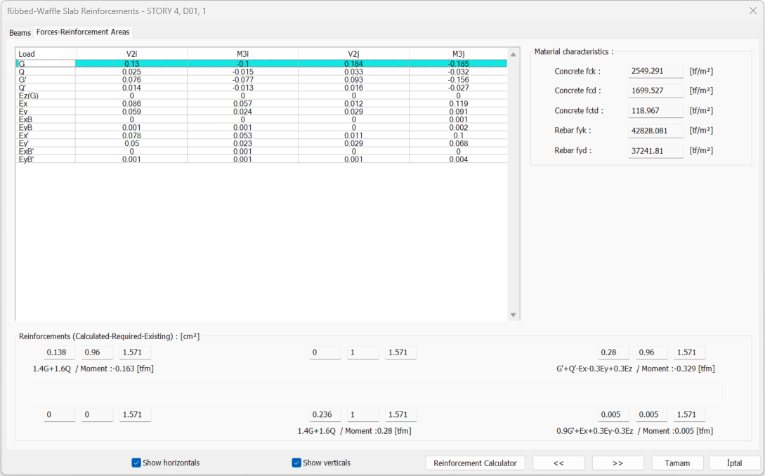
Forces - Reinforcement Areas Tab
|
Specifications |
|---|
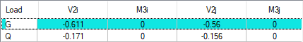
Load: The name of the respective load or load combinations.
|
|
Reinforcements (calculated-required-existings) 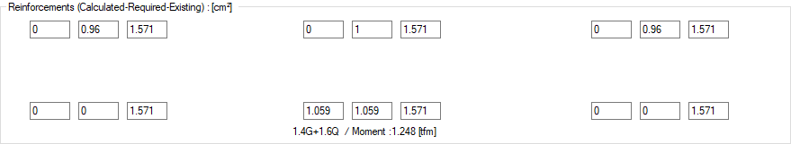
In the left support of the beam, upper and lower; in the middle; clearance and mounting; in the right bracket; The total of existing/required and surplus rebar areas are given as top and bottom. Just below, the loading combination of the rebar calculation and the moment values of that combination are also written. |
|
Concrete fck The characteristic of concrete is its compressive strength. |
|
Concrete fcd The characteristic calculation of concrete is its compressive strength. |
|
Concrete fctd The characteristic calculation of concrete is its tensile strength. |
|
Rebar fyk Reinforcement is the yield strength of rebar. |
|
Rebar fyd It is the calculation strength of rebar steel. |
Next Topic
Related Topics