The Complete Message:
B1 Irregularity in (X / Y) direction is not provided. Increase system rigidity
B1 - Strength Irregularity Between Neighboring Floors (Weak Floor) occurs when the effective cutting area of one floor is less than the value specified in the regulation when compared to an upper floor. The variables in the cutting area are curtain, column and walls (nth). Effective cutting areas are automatically calculated according to the load-bearing system and wall-wall loads entered in the program, and the values are printed in the general report of the earthquake regulation.
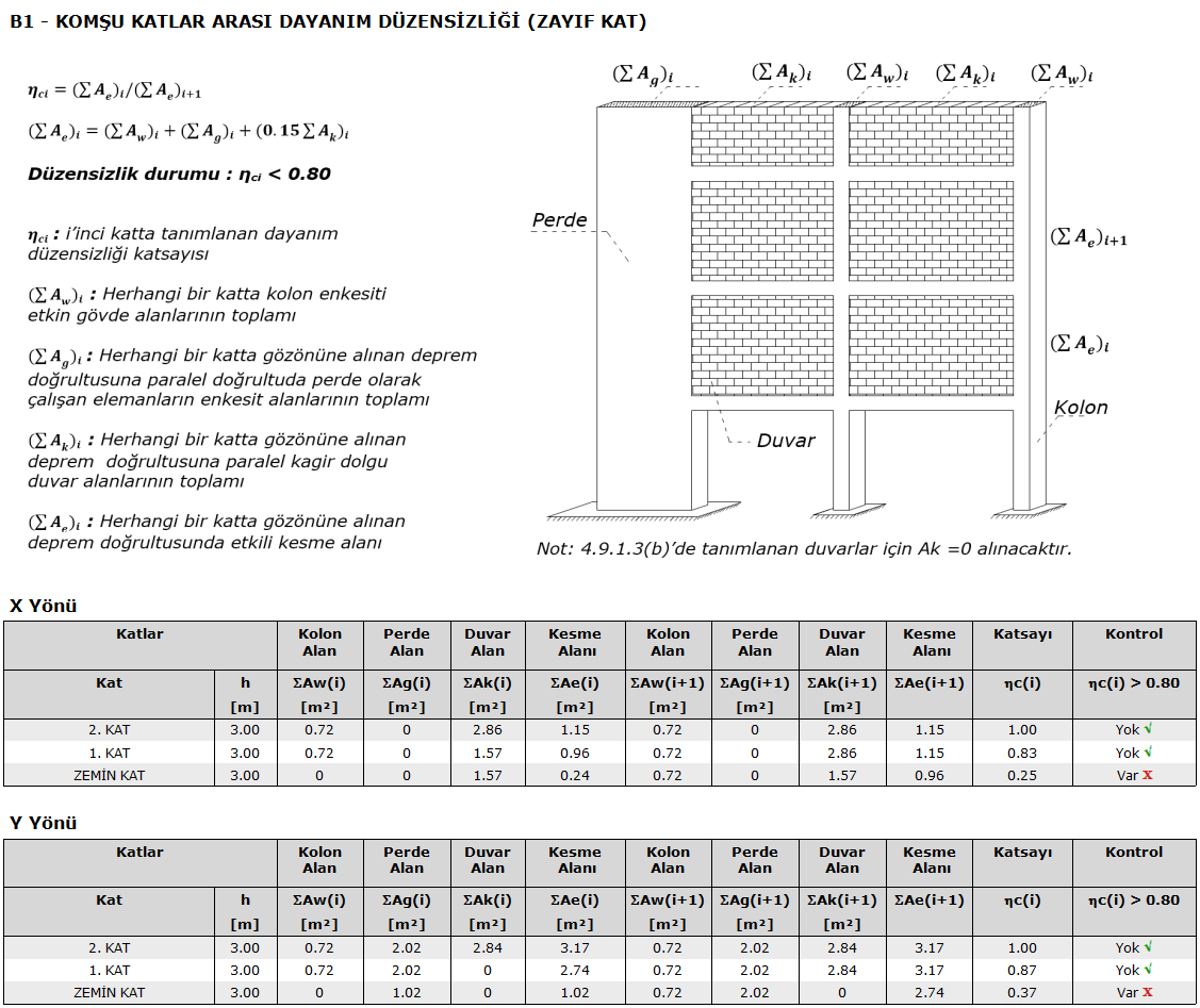
In the buildings with B1 type irregularity in TBDY 2018 Article 3.6.2.1 , if the sum of the filling wall areas on the i'th floor is more than the upper floor, the filling walls will not be taken into account in the calculation of ηci. Considering the floor where ηci is the smallest, the load-bearing system behavior coefficient given in Table 4.1 in the range of 0.60 (η ( ci min ) <0.80 shall be multiplied by 1.25 (ηci min) value and applied to the whole building in both earthquake directions. However, it will never be ηci <0.60. Otherwise, the earthquake calculation will be repeated by increasing the strength and stiffness of the weak floor.
There are two situations in the above article.
-
0.60 η η ( ci min ) <0.80 range
The carrier system behavior coefficient R is multiplied by 1.25 (ηci min) value and automatically dropped by the program and the R coefficient is given as information under the title of R coefficient selection reason in the Earthquake Regulation General Report. The user does not need to take any action.
-
Having ηci <0.60
B1 Irregularity in (X / Y) direction is not provided. Increase system stiffness, message is given. It should be ensured that it is ηci> 0.60.
Possible solutions:
-
More columns, curtains, curtain groups etc. in the requested direction. You can add a vertical carrier system, increase the size and / or change the direction of the columns.
-
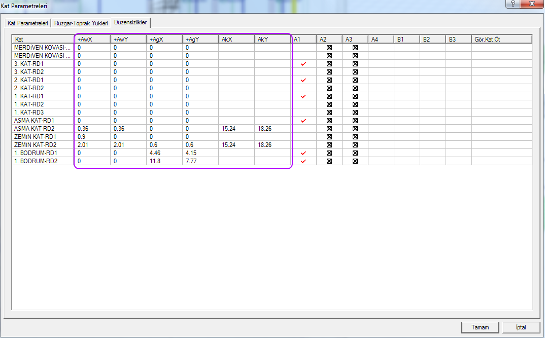
The cutting areas are provided in the Irregularities tab of the Floor Parameters dialog, and the values can be changed as in the example image below.