
Beams and columns are automatically modeled as frame (bar) finite elements.
All 6 degrees of freedom are considered at the joints of columns and beams.
If slabs are modeled as rigid diaphragms, those that correspond to rigid motion of these degrees of freedom are removed.
A shell model is created automatically according to the finite element method for shearwalls.
Reinforced concrete walls are modeled automatically with shell finite elements that contain degrees of freedom for both in-plane and out-of-plane displacements according to ACI 318-19 R11.4.1.3.
İnternational Design Codes
ASCE 7-16 : Structural Modeling with Finite Element Method per ASCE 7-16
TSC 2018 : Finite Elements - Frame Element (4.5.2.1)
In general, the same three-dimensional model is used for the equivalent lateral force, the modal response spectrum, and the linear response history analysis procedures. Five percent of critical damping is automatically included in the modal response spectrum approach.
For reinforced concrete buildings, it is important to consider the effects of axial, flexural, and shear cracking in modeling the effective stiffness of the structural elements. It is automatically applied for reinforced concrete structures elements according to the regulation.
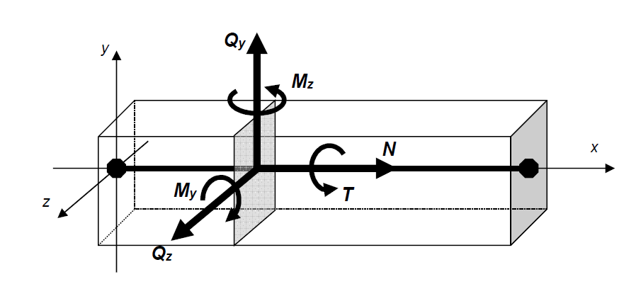
Reinforced concrete and steel columns and beams are automatically modeled and analyzed by using a frame model in accordance with the finite element method with 6 degrees of freedom.
There are 6 freedoms in total, 3 translation vectors and 3 rotation vectors at one end of the frame elements. In this case, for a 3-dimensional analysis, a node must have 6 deformation results.
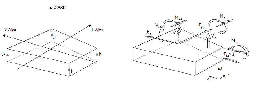
Similarly, there are a total of 6 freedoms, 3 translation vectors and 3 rotation vectors, at the nodes of the shell elements. However, while creating internal force diagrams in frame elements, stress results occur in shell elements.
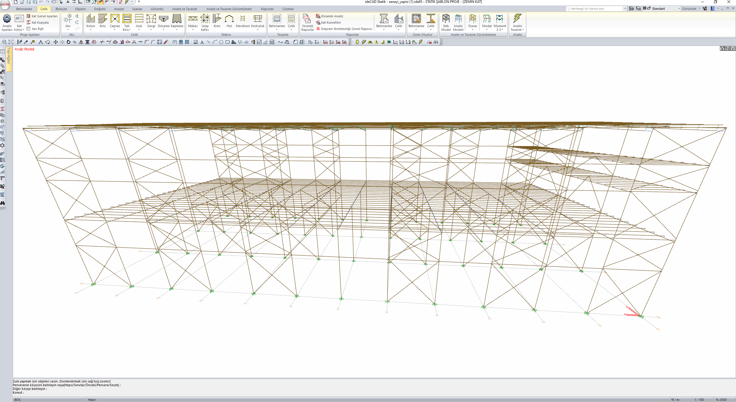
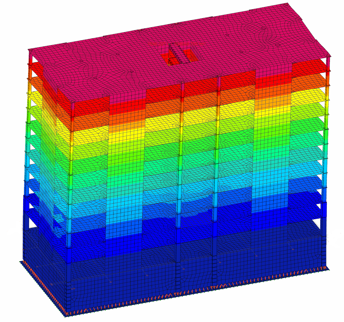
In the picture below, an analysis model and deformation shape of a sample structure modeled in 3D can be seen. As you can see, each node has 6 displacement values, 3 of which are translation and 3 rotations.
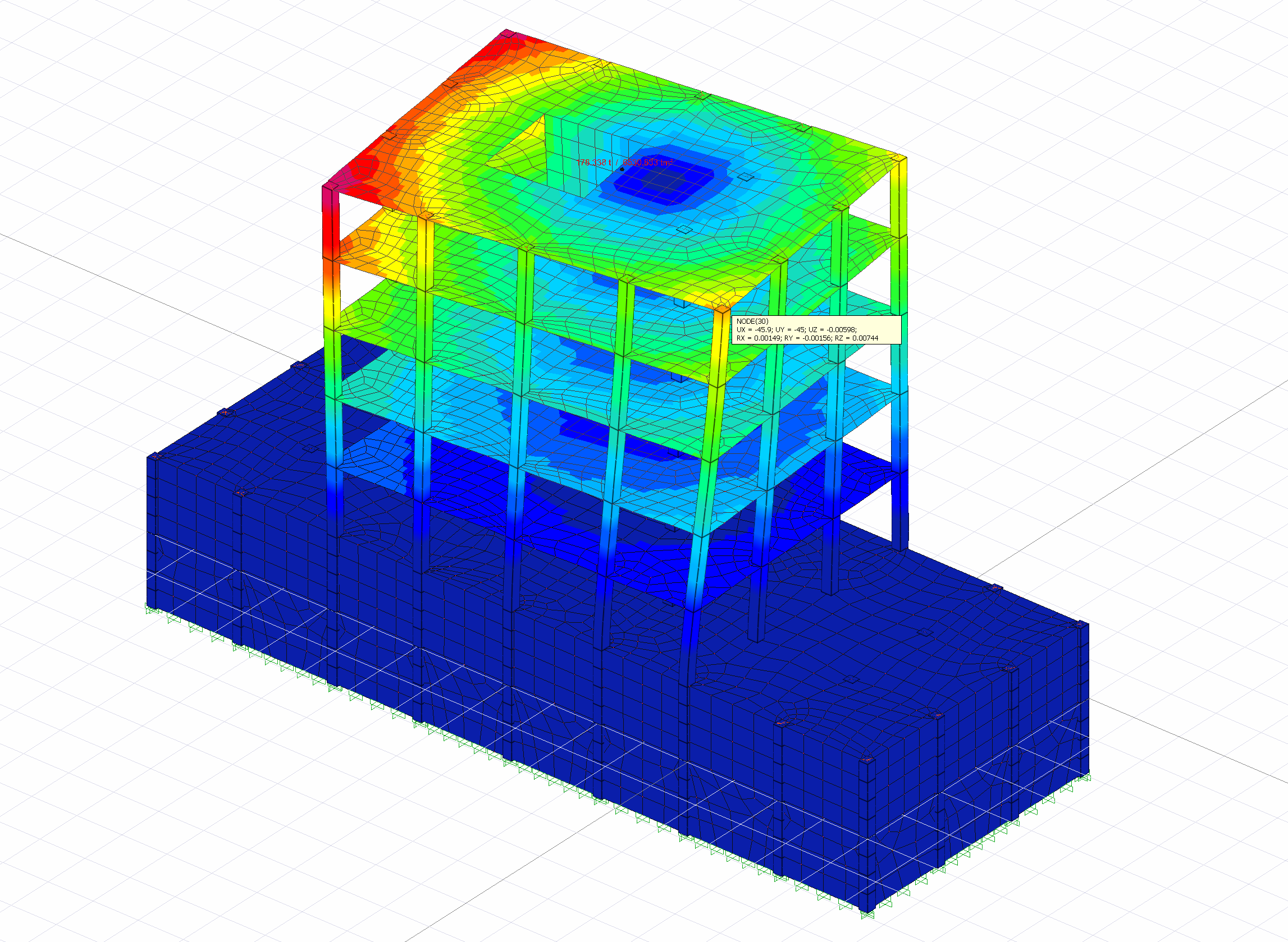
According to the finite element method, finite element width can be changed from the program interface according to the sensitivity of the calculation to be made in the walls. After the analysis, the deformations of the shearwalls is displayed.
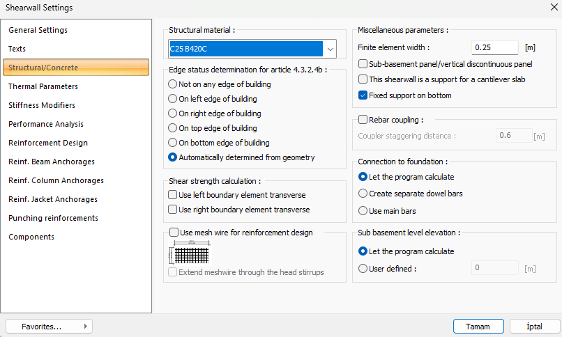
Reinforced concrete walls are modeled automatically with shell finite elements that contain degrees of freedom for both in-plane and out-of-plane displacements according to Codes. Other modeling rules are also applied automatically.
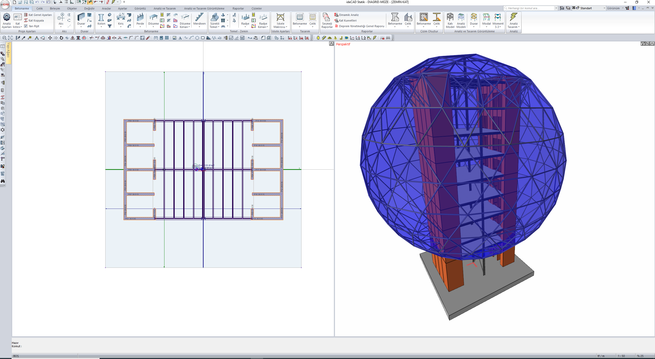
In the pictures below, a structure and analysis model with different geometry modeled in 3 dimensions and semi -rigid is shown.
Next Topic