
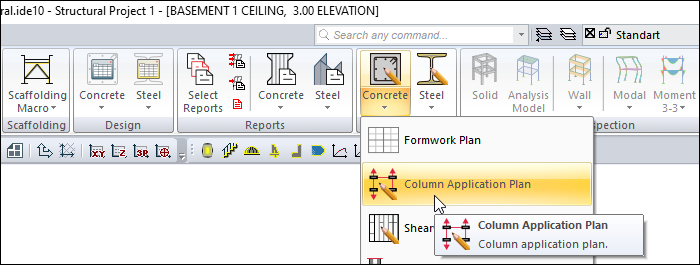
Column application plan of the project is prepared with the Column Application Plan command.
Location of the Column Application Plan Command
You can access it under the ribbon menu Concrete tab, Create Drawing heading.
Usage Steps
-
Click on the Column Application Plan icon.
-
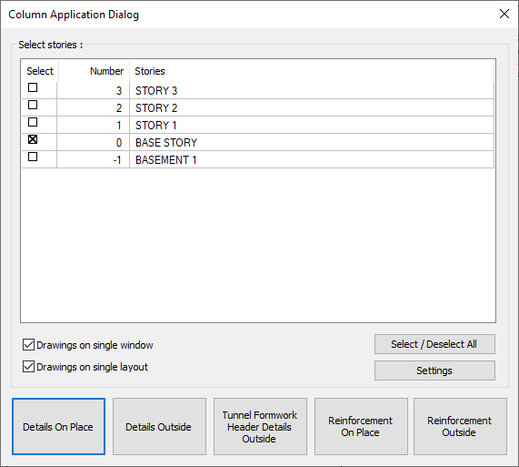
The column application dialog will open.
-
In the drawing properties dialog that opens when you click the Settings button, you can make the desired edits and click the OK button.
-
Click one of the options: details on place, details outside, tunnel formwork header details outside, reinforcement on place and reinforcement outside.
-
According to the option you clicked, a column application plan will be prepared.
Column Application Dialog
|
Specifications |
|
Select stories 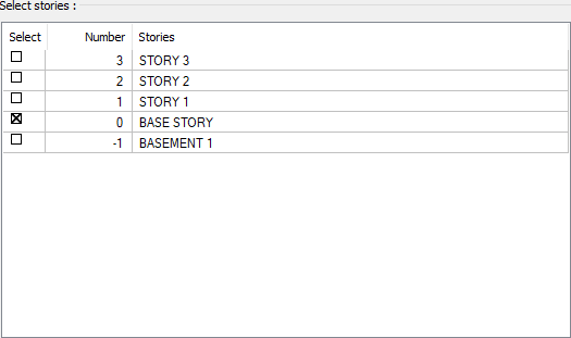
Mark the stories for which you want to get a column application plan. |
|
Drawings on single window Column application plans of all marked stories are prepared in a single operating window. If the option is not selected, each story will be applied in separate working windows. |
|
Drawings on single layout Column application plans of all marked stories are placed in a single layout. If the option is not selected, each layer will be applied as separate layouts. |
|
Select/Deselect all It marks all stories or cancels those with a sign. |
|
Settings Opens the dialog where drawing properties can be set. |
|
Details on place 
When applying the columns, it also enlarges them and details them on site. |
|
Details outside 
While applying the columns, leaves them in 1/50 plan view and prepares the details separately at the edge of the sheet. |
|
Tunnel formwork header details outside 
It prepares the applications of tunnel formwork projects. |
|
Reinforcement on place 
Prepares the applications of the reinforcement projects. This option also enlarges and elaborates the columns on the spot when applying. |
|
Reinforcement outside 
Prepares the applications of the reinforcement projects. This option leaves them in 1/50 plan view while applying the columns and prepares the details separately at the edge of the sheet. |
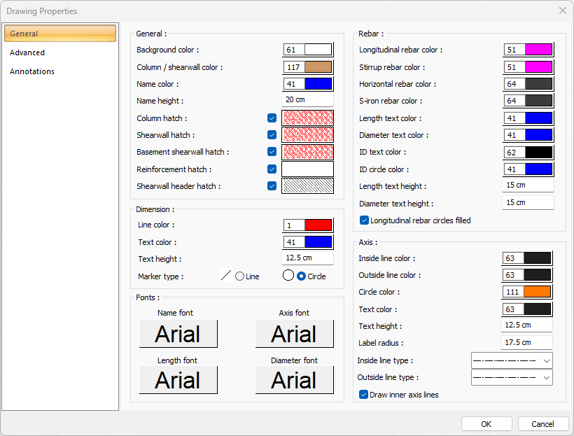
Settings - Drawing Properties
General Tab
|
Specifications - General |
|
Background color Sets the background color. When the color box is clicked, the appropriate color is selected from the window that opens. |
|
Column/shearwall color Sets the column/shearwall color. When the color box is clicked, the appropriate color is selected from the window that opens. |
|
Name color Sets the name color. When the color box is clicked, the appropriate color is selected from the window that opens. |
|
Name height Name height is entered. |
|
Column hatch It is the hatch type that is valid for column. Clicking on hatch opens the Hatch Settings dialog. The hatch type is selected from the hatch table in this dialog. |
|
Shearwall hatch It is the hatch type that is valid for shearwall. Clicking on hatch opens the Hatch Settings dialog. The hatch type is selected from the hatch table in this dialog. |
|
Basement shearwall hatch It is the hatch type that is valid for basement shearwall. Clicking on hatch opens the Hatch Settings dialog. The hatch type is selected from the hatch table in this dialog. |
|
Reinforcement hatch It is the hatch type valid for reinforcement. Clicking on hatch opens the Hatch Settings dialog. The hatch type is selected from the hatch table in this dialog. |
|
Shearwall header hatch It is the hatch type valid for shearwall header. Clicking on hatch opens the Hatch Settings dialog. The hatch type is selected from the hatch table in this dialog. |
|
Specifications - Dimensions |
|
Line color Sets the dimension line color. When the color box is clicked, the appropriate color is selected from the window that opens. |
|
Text color Adjusts the text color. When the color box is clicked, the appropriate color is selected from the window that opens. |
|
Text height Size text height is entered. |
|
Marker type The marker type is selected. |
|
Specifications - Fonts |
|
Name font 
Name font is selected. |
|
Axis font 
Axis font is selected. |
|
Length font 
The font of the length text is selected. |
|
Diameter font 
Diameter font is selected. |
|
Specifications - Rebar |
|
Longitudinal rebar color Sets the longitudinal rebar color. When the color box is clicked, the appropriate color is selected from the window that opens. |
|
Stirrup rebar color Sets the stirrup rebar color. When the color box is clicked, the appropriate color is selected from the window that opens. |
|
Horizontal rebar color Sets the horizontal rebar color. When the color box is clicked, the appropriate color is selected from the window that opens. |
|
S-iron rebar color Sets the s-iron rebar color. When the color box is clicked, the appropriate color is selected from the window that opens. |
|
Length text color Sets the color of the length text. When the color box is clicked, the appropriate color is selected from the window that opens. |
|
Diameter text color Sets the color of the diameter text. When the color box is clicked, the appropriate color is selected from the window that opens. |
|
ID text color Adjusts the color of the ID text. When the color box is clicked, the appropriate color is selected from the window that opens. |
|
ID circle color Sets the ID circle color. When the color box is clicked, the appropriate color is selected from the window that opens. |
|
Length text height Text height is entered. |
|
Diameter text height Diameter text height is entered. |
|
Longitudinal rebar circles filled When the option is selected, the inside of the longitudinal rebar circle is filled. |
|
Specifications - Axis |
|
Inside line color Sets the axis inside line color. When the color box is clicked, the appropriate color is selected from the window that opens. |
|
Outside line color Sets the axis outside line color. When the color box is clicked, the appropriate color is selected from the window that opens. |
|
Circle color Sets the axis circle color. When the color box is clicked, the appropriate color is selected from the window that opens. |
|
Text color Adjusts the text color of the axis. When the color box is clicked, the appropriate color is selected from the window that opens. |
|
Text height Text height of the axis is entered. |
|
Label radius The radius of the axis label is entered. |
|
Inside line type The line type of the axis inside line is selected. Clicking the down arrow buttons to the right of the boxes opens the list of line types. From this list, the desired line type is selected by clicking with the left mouse button. |
|
Outside line type The line type of the axis outside is selected. Clicking the down arrow buttons to the right of the boxes opens the list of line types. From this list, the desired line type is selected by clicking with the left mouse button. |
|
Draw inner axis lines When the option is selected, axis inner lines are drawn. |
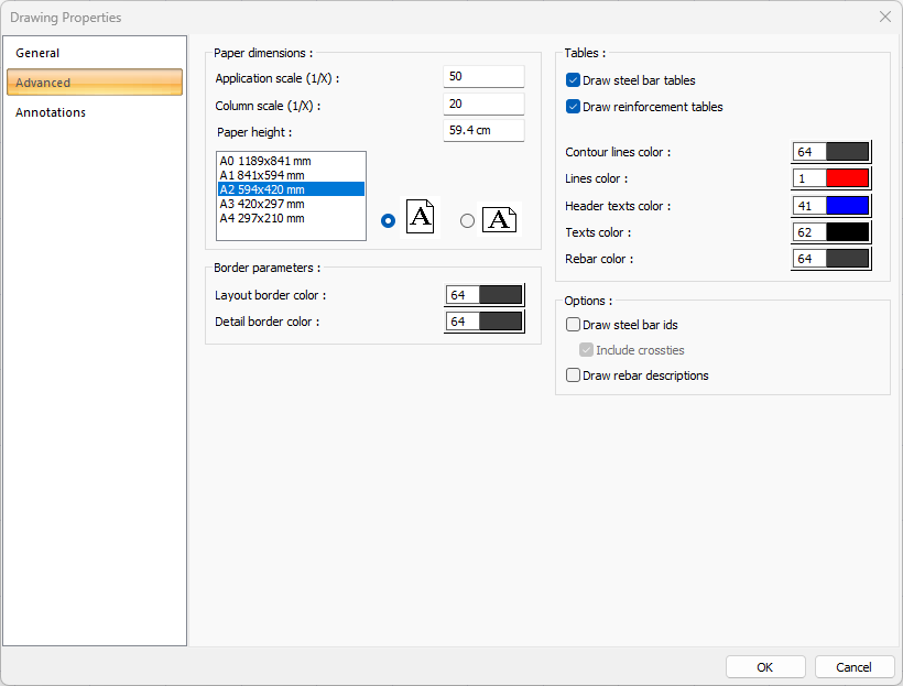
Advanced Tab
|
Specifications |
|---|
|
Application scale (1/X) Application scale is entered. |
|
Column scale (1/X) The column scale is entered. |
|
Paper height Standard paper sizes can also be selected, and any paper size value can be entered. |
|
Standard paper sizes Standard paper sizes are listed. The layout size can be selected from the list, as well as the layout dimensions can be determined by entering the width and height values. |
|
Vertical/Horizontal use It is determined whether the layout will be used horizontally or vertically. |
|
Layout border color You can select the layout border color from the color palette that appears when you click it. If clicked together with the Shift key, the pen thickness of the relevant color can be adjusted. The pen thickness value entered here is only used in inkjet printers. |
|
Detail border color You can select the detail border color from the color palette that appears on the screen when you click it. If clicked together with the Shift key, the pen thickness of the relevant color can be adjusted. The pen thickness value entered here is only used in inkjet printers. |
|
Draw steel bar tables If checked, rebar tables are added to the drawing. |
|
Draw reinforcement tables If checked, the object reinforcement table is added to the drawing. |
|
Contour lines color Sets the color of the table contour lines. When the color box is clicked, the appropriate color is selected from the window that opens. |
|
Line color Sets the color of the table lines. When the color box is clicked, the appropriate color is selected from the window that opens. |
|
Header text color Sets the color of the table header texts. When the color box is clicked, the appropriate color is selected from the window that opens. |
|
Text color Sets the color of table text. When the color box is clicked, the appropriate color is selected from the window that opens. |
|
Rebar color Sets the color of the rebar. When the color box is clicked, the appropriate color is selected from the window that opens. |
|
Draw steel bar ids If checked, theids of the rebars are shown in the drawings. If not checked, it will not be displayed. If desired, crossties are included. |
|
Draw rebar descriptions If checked, the rebar descriptions are shown in the drawings. |
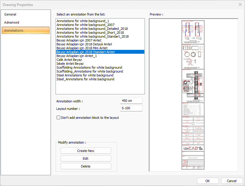
Annotations Tab
|
Specifications |
|---|
|
Select an annotation from the list 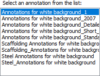
Defined annotations are listed. |
|
Preview 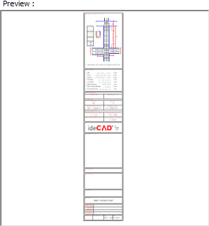
There is a preview of the annotation selected from the list. |
|
Annotation width Annotation width is determined. |
|
Layout number The layout number is determined. |
|
Create New The new annotation is created. |
|
Edit The annotation is edited. |
|
Delete The annotation is deleted. |
|
Don’t add annotation block to the layout If it is checked, annotation will not be added to the layouts. |
Next Topic