
Notations
A : Gross cross-sectional area of member
Aeff : Effective area
E : Modulus of Elastisity
fy : Specified minimum yield stress of the type of steel being used
Ncr : the elastic critical force for the relevant buckling mode
Torsional Buckling Limit State
Buckling occurs when the element rotates around its longitudinal axis. The limit state of torsional buckling is applicable to axially loaded columns with doubly symmetric open sections with very slender cross-sectional elements consisting of 4 corners placed back to back.
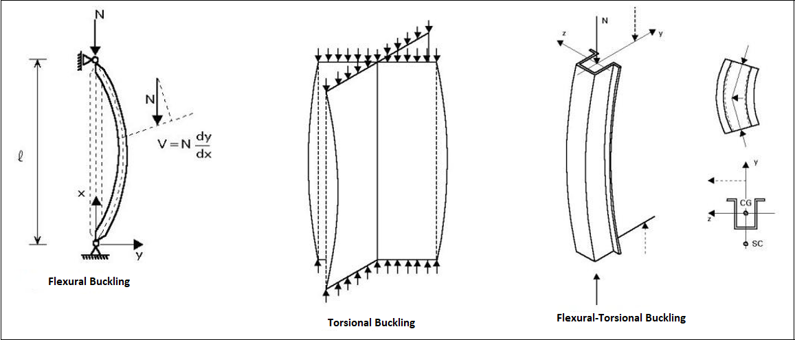
Flexural-Torsional Buckling Limit State
The buckling deformations consist of a combination of twisting and bending about two flexural axes of the member.
The symmetry axis is the y-axis, where the buckling around the y-axis is caused by the tilting and rotation of the element around its longitudinal axis. The limit state of flexural-torsional buckling is applicable to columns with singly symmetric shapes, such as double angle, T- and U-shapes and asymmetric cross-sections.
Slenderness for torsional and torsional-flexural buckling is determined according to Eq. 6.52 and Eq. 6.53.
for Class 1,2 and 3
for Class 4 cross-section
Next Topic