
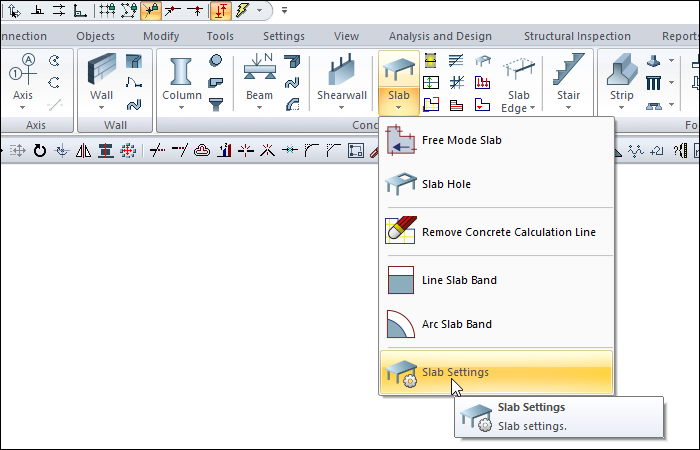
With the Slab Settings command, settings such as concrete slab size, elevation, material selection, structural material, rib and waffle slab tooth dimensions are accessed.
Location of the Slab Settings Dialog
Slab toolbar that appears on the screen after the slab command is run, by clicking the Setting icon.
A dialog is also opened when double clicked on an entered slab.
Also, it can be accessed by clicking on the Concrete tab Concrete title.
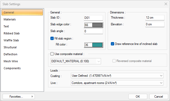
General Tab
|
Specifications |
|---|
|
Slab ID It is the name of the slab. The number increases according to the order of drawing the slab (D01, D02, D0 etc.). If desired, the slab names can be changed later with the Label Entities command. |
|
Slab color The color of the tile border lines is adjusted. Click on the color box with the left mouse button and move the mouse cursor over the opened color palette. The button is released when the wanted color is reached. The color box turns into the selected color. If the color box is clicked on the keyboard with the shift key, the pen thickness of the corresponding color can be adjusted. |
|
Slab angle Normal value is zero. In a system that is defined with the bevel to objects command, the program automatically determines the angle of the slab with the base and the angle value of the slab with the base appears here. |
|
Fill slab region If the option is selected, the area within the slab boundaries will be shown painted in the plan. |
|
Fill color The color in which the inside of the slab will be painted is adjusted. Click on the color box with the left mouse button and slide the mouse cursor over the opened color palette. When the desired color is reached, the key is released. The color box turns into the selected color. If the color box is clicked with the shift key on the keyboard, the pen thickness of the relevant color can be adjusted. |
|
Draw reference line of inclined slab It is used to show the reference axis of the floors (inclined slabs) with an angle different from zero degrees with the slab in the plan. |
|
Thickness The slab height is entered. The slab starts from the floor ceiling and hangs down to the given height. If the slab height is increased, the slab becomes thicker downwards. |
|
Elevation The slab level is entered. When the elevation is zero, the slab top surface is flush with the floor ceiling. If a positive value is entered, the slab rises from the floor ceiling, if a negative value is entered, it falls under the story ceiling. Negative value is entered to obtain low slab. |
|
Use composite material 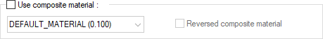
Composite materials allow the slab to be drawn in a different material view in cross-section. If checked, it allows the use of materials defined in the "Composite Material" editor. After the row is marked, one of the composite materials in the list below is selected with the left mouse button. Changes the appearance of the slab in section according to the selected composite material. |
|
Reversed composite material If marked, the materials used in the slabs are reversed. When the section is taken, the top hatching in the site section area appears at the bottom and the bottom hatch at the top. |
|
Coating 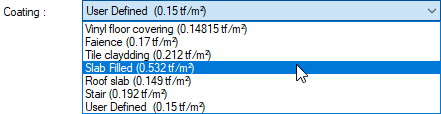
The appropriate value for the coating load is selected from the list. The values listed in the list are the values defined in the slab load library and are prepared only for the slab weight. The reinforced concrete weight of the slab will be added automatically during analysis. If you want to use another value instead of using one value in the list, select "user-defined" from the list and enter a value. In ribbed and cassette slabs, concrete weight is added automatically during analysis. |
|
Live 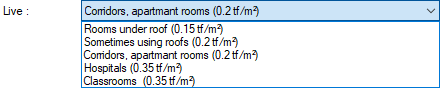
Select the appropriate value for live load from the list. The values that appear in the list are the values defined in the slab load library. If you are going to use another value instead of using one value in the list, select "user defined" from the list and enter a value. |
Materials Tab
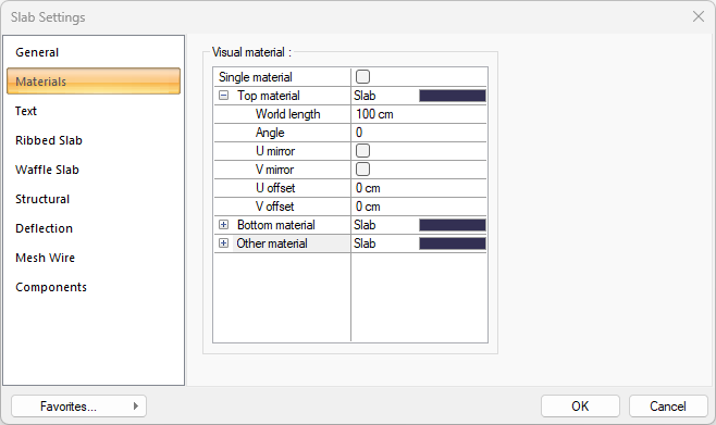
The material to be covered in renderings of the slabs is selected. The selected slab is covered with material and displayed in renderings like this.
|
Specifications |
|---|
|
Single material By selecting the single material option, the material selected in "Top material" is used on all surfaces of the slab. |
|
Top material The material to be used on the top surface of the slab is selected from the list. The material list window opens with the left mouse button. The material is selected from the opened material list. The materials must be predefined. |
|
Bottom material The material to be used on the bottom surface of the slab is selected from the list. The material list window opens with the left mouse button. The material is selected from the opened material list. The materials must be predefined. |
|
Other material The material to be used on the surfaces other than the top and bottom surfaces of the slab is selected from the list. The material list window opens with the left mouse button. The material is selected from the opened material list. The materials must be predefined. |
|
World length World length is entered. For example; If 1 is entered, the selected material texture is taken as 1 meter and covered on the relevant roof. If the texture is thought to be in the form of a square, the object surfaces are covered with 1x1 textures arranged side by side. It can be determined separately for each surface. |
|
Angle The texture angle is entered. |
|
U mirror It takes the mirror of the texture with respect to the y plane. |
|
V mirror It takes the mirror of the texture with respect to the x plane. |
|
U offset The motion value of the texture in the x plane is entered. |
|
V offset The motion value in the y plane of the texture is entered |
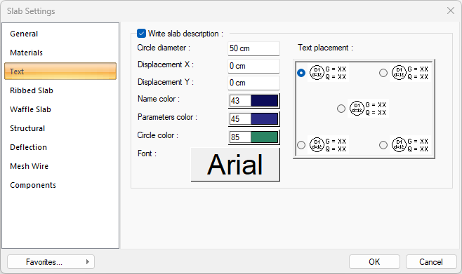
Text Tab
|
Specifications |
|---|
|
Write slab description It is marked if it is wanted to write the slab name, height and load information on the slab. |
|
Circle diameter The slab is the label circle diameter. |
|
Displacement X/Y Give the horizontal and vertical offset distances according to the installed position of the slab circle. |
|
Name Color The tile is the name color. To select a color, click and hold the left mouse button on the color box and slide it on the color palette that opens and select the color you want. |
|
Parameters color The color of the covering, live load and slab height text defined on the slab is adjusted. |
|
Circle color The color of the circle that includes its height is set with the name of the slab. To select a color, click and hold the left mouse button on the color box and slide it on the color palette that opens and select the color you want. |
|
Text placement 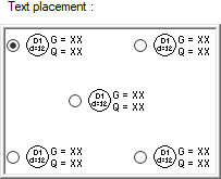
The location of the slab text on the slab is chosen. |
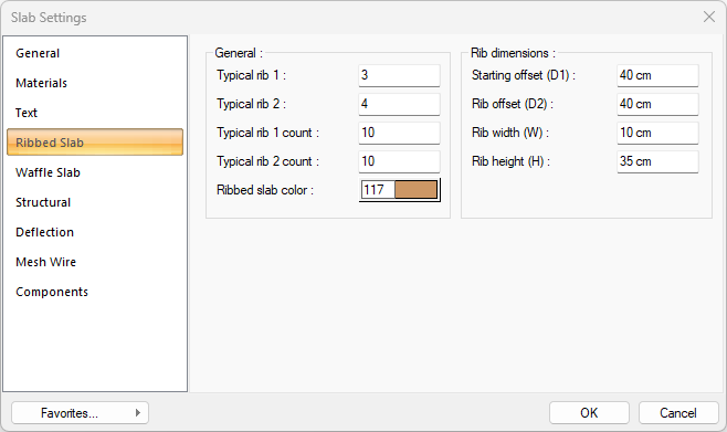
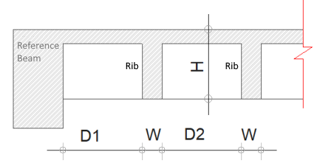
Ribbed Slab Tab
Ribbed slab is ribs slab in one line. Two typical rib can be identified in the rib.
|
Specifications |
|---|
|
Typical rib 1 It indicates which rib will be the 1st calculation rib from the rib drawing axis (beam, axis etc. or the axis created by clicking two points). The static properties of the respective rib should be taken into account when making a selection. |
|
Typical rib 2 From the rib drawing axis (beam, axle, etc. or the axis created by clicking two points), write which rib will be the 2nd calculation rib. The static properties of the respective rib should be taken into account when making a selection. |
|
Typical rib 1 count Determines how many ribs the typical rib 1 reinforcement will be used for. The program calculates this value automatically. However, it can be intervened if desired. The value written here affects the length of the rib. |
|
Typical rib 2 count Determines how many ribs the typical rib 2 reinforcement will be used for. The program calculates this value automatically. However, it can be intervened if desired. The value written here affects the length of the rib. |
|
Ribbed slab color Select the color of the rib lines. |
|
|
Starting offset (D1) The distance from the reference beam or reference direction axis to the face of the initial rib beam (tread). |
|
Rib offset (D2) It is the clean distance between two ribs. |
|
Rib width (W) It is the width of the rib. |
|
Rib height (H) It is the height of the rib. |
Waffle Slab Tab
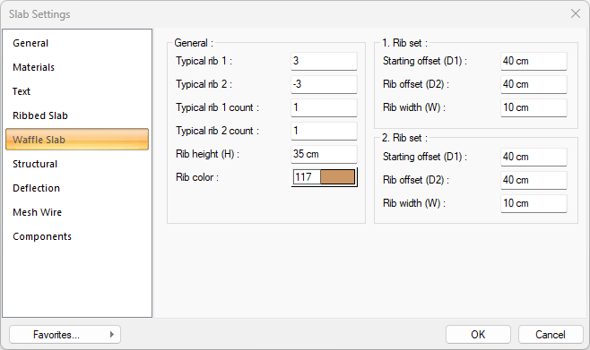
Waffle slab is two-way rib slabs. Unlike the rib object, there is one rib in each direction on the waffle.
|
Specifications |
|---|
|
Typical rib 1 It specifies which thread will be the 1st calculation tooth starting from the drawing axis (beam, axis etc. or the axis created by clicking two points). The static properties of the respective rib should be taken into account when making a selection. |
|
Typical rib 2 It specifies which tooth will be the second calculus tooth starting from the drawing axis (beam, axis etc. or the axis created by clicking two points). The static properties of the respective rib should be taken into account when making a selection. |
|
Typical rib 1 count Determines how many cassette rib the first typical rib reinforcement will be used for. The program calculates this value automatically. However, it can be intervened if wanted. The value written here affects the length of the rib. |
|
Typical rib 2 count Determines how many cassette rib the typical rib reinforcement will be used for. The program calculates this value automatically. However, it can be intervened if wanted. The value written here affects the length of the rib. |
|
Rib Color Choose the color of the rib lines. |
|
|
|
Starting offset (D1) The distance from the reference beam or reference direction axis to the face of the initial rib beam (tread). |
|
Rib offset (D2) It is the clean distance between two ribs. |
|
Rib width (W) It is the width of the rib. |
|
Rib height (H) It is the height of the rib. |
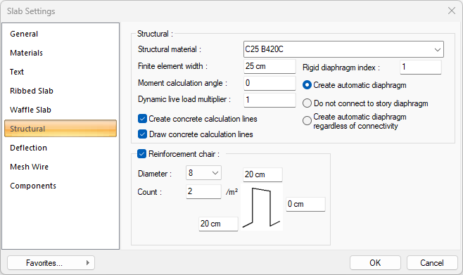
Structural Tab
|
Specifications |
|---|
|
Structural material Select the structural material to be used in the element from the list. Structural material can be defined as a reinforced concrete element under Materials in Building Tree. |
|
Finite element width Enter the maximum finite element width to be taken as basis in the slab calculation. The program performs slab analysis by dividing tiles into trapezoidal finite elements. Finite element width is automatically adjusted according to the slab shape, provided that it does not exceed the value entered in this row. |
|
Moment calculation angle When this value is left zero, the slab axes are taken as 0 degrees in the 1st direction and 90 degrees in the 2nd direction during the slab analysis. In a rotated structure, the moment calculation angle is also refreshed automatically. The value can be changed when slab analysis is desired to be performed according to the axis at different angles. 1. The structure is defined parallel to the x axis. When the torque angle is 0 degrees, the following moment diagram is obtained. 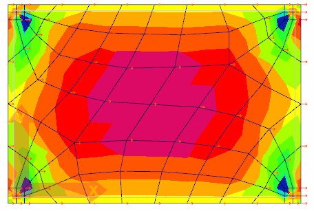
2. If the structure is rotated 45 degrees and the moment angle is given 45 degrees, the same results as 1 are obtained. 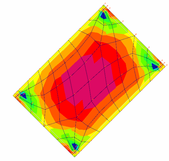
3. If the moment angle is left zero in a structure that is entered as 45 degrees, results different from 1 and 2 will be obtained. 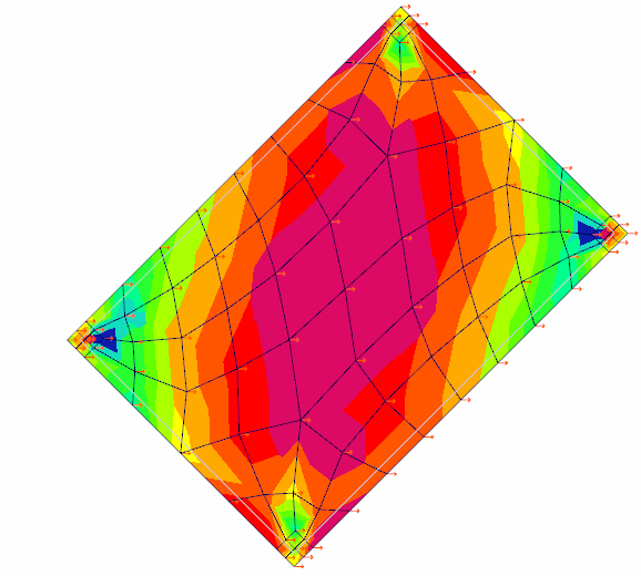
|
|
Dynamic live load multiplier While calculating the total weight of the building, the live load value coming from the relevant slab is taken into account by multiplying it with the value entered in the box. In the earthquake load calculation, element design results change as the total mass of the building will change. However, this multiplier does not change the live load value on the slab. |
|
Create concrete calculation lines When the slab is placed, this option can be selected to automatically create the reinforced concrete calculation axis for the slab. In this case, two horizontal and vertical reinforced concrete calculation axis are created in the middle of the floor in each defined floor. If the option is not selected, the user must define the reinforced concrete calculation axis using the "reinforced concrete calculation axis" command. |
|
Draw concrete calculation lines If it is wanted to show the reinforced concrete calculation axis showing the direction in which the slab reinforced concrete will be made, it is marked. This representation is for informational purposes only and is not drawn in the formwork and / or reinforcement plans. |
|
Rigid diaphragm index 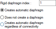
Rigid diaphragms are automatically detected by the program according to the presence / absence of slab on any slab. These parameters change the rigid diaphragm conditions on a slab basis. The changes made affect the analysis. Rigid diaphragm index It is the number that groups rigid diaphragms. For example, in projects with a single rigid diaphragm, this value is 1 for all floors. In systems with different rigid diaphragms, diaphragms will be indexed as 2, 3 etc. Create automatic diaphragm When the option is selected, the slab will be included in the rigid diaphragm index determined according to the rigid diaphragm index. All slabs with the same index number will be in the same rigid diaphragm. Do not connect to story diaphragm When the option is checked, the slab will not be found on the rigid diaphragm. Create automatic diaphragm regardless of connectivity Regardless of the position of the slab when the option is selected, slabs according to the number written in the rigid diaphragm index will be accepted within the same rigid diaphragm system. For example, this option may be needed in systems with two towers with space in between. |
|
Reinforcement chair By selecting the option, the reinforcement chair is defined for the slab. |
|
Diameter The diameter of the reinforcement chair is entered. |
|
Count The number of reinforcement chair per square meter is entered. |
|
Reinforcement chair 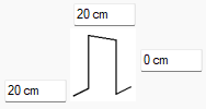
The dimensions of the reinforcement chair are entered. The height of the reinforcement chair is found by subtracting the concrete slab height. The negative or positive value to be written to the height is added to the height value calculated by the program. |
Deflection Tab
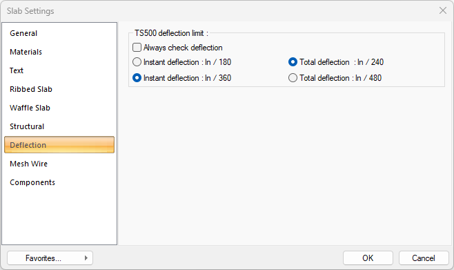
TS500 Deflection limits: Give deflection control upper limits. Values taken from TS500. If the "Always check deflection condition" option is selected, the instantaneous and temporal deflection control is performed on the slabs even if the "deflection condition is a height condition that does not require deflection control" is checked.
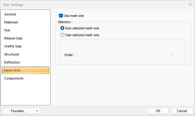
Mesh Wire Tab
|
Specifications |
|---|
|
Use mesh wire Check the option to design ready reinforcement on the object. |
|
Auto selected mesh wire Check this option if you want to design the mesh wire selection as the choice made by the program as a result of the analysis. The program will use the most suitable mesh wire according to the calculation. |
|
Use selected mesh wire Regardless of the analysis result, if you want the program to use the reinforcement you have provided as mesh wire, check this option. Next, select mesh wire from the list to use under. |
|
Under 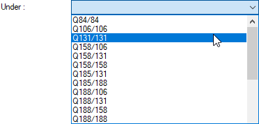
For user-defined mesh wire, select the reinforcement to be used under the section. |
Building Components
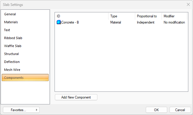
Add Building Components: Assigns the projected building materials to the object for detailed building components metrics.
-
Click on the building components button.
-
The Component Selection dialog will open.
-
In this dialog, click on the folder related to the material from the list on the left. Click on the material you want to use.
-
Set the parameters on the right.
-
Click the OK button. The "Component Selection" dialog will be closed. A summary line of the material will appear in the Building Components tab. More than one material assignment to an object can be done this way.
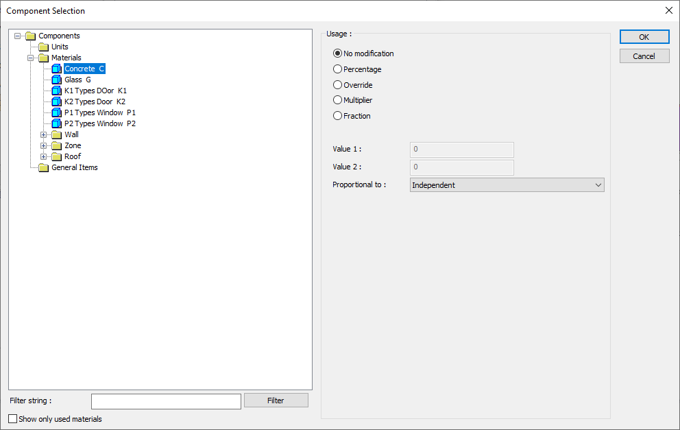
In the usage section
No modification: The amount of material to be assigned for the object in question is marked when it is desired to be used in the size that was previously specified in the material definition.
Percentage: This line is marked when it is desired to be used with the percentage of the amount previously determined in the material definition, as much as the value entered in the "Value 1" line in the same dialog. For example, if the material quantity is 70, if the line “Value 1” says 40, it means the material amount will be used up to 40 * 70%.
Override: This line is marked so that the quantity entered in the “Value 1” line in the same dialog will be used instead of the quantity previously determined in the material definition.
Multiplier: This line is marked in order to use the value found at the end of the multiplication of the value entered in the "Value 1" line in the same dialog with the amount previously determined in the material definition.
Fraction: This line is marked so that the amount determined in the material definition before will be used as the fraction value created by the values entered in the "Value 1" and "Value 2" lines in the same dialog. "Value 1" is the denominator "Value 2" is the denominator.
Proportional to: It is determined to what scale-area, circumference, length etc.-, region-side area, top, edge etc.- the material will be proportioned to. The content of the proportional list box is automatically determined according to the object and the size of the material. For example, a different list will be created if an operation is made for the column, a different list will be created for the library, a different list for the volume, and a different list for the field.
The lines that appear in the Proportion list according to the slab object and material size are as follows:
|
Slab |
||
|
Measure |
Listed |
Explanation |
|
Constant |
Independent |
The fixed measure used will be used exactly as the amount. |
|
Length |
Independent |
It means that the length measure found while defining the material will be used exactly as the length value. |
|
Perimeter |
It means that the length of the material will be found by multiplying the perimeter of the slab with the length measure found while defining the material. |
|
|
Area |
Independent |
It means that the area measure found while defining the material will be used exactly as the amount. |
|
Top area |
The value to be found by multiplying the area measure found when defining the material with the area of the surface remaining on the slab means to be used as the material area. |
|
|
Bottom area |
It means that the value to be found by multiplying the area measure found while defining the material and the area of the surface under the slab will be used as the material area. |
|
|
Top and bottom area |
The value found by multiplying the area measure found when defining the material and the sum of the surface areas on the upper and lower sides of the slab will be used as the material area. |
|
|
Volume |
Independent |
It means that the volume measurement found when defining the material will be used exactly as the volume value. |
|
Volume |
It means that the volume measurement found when defining the material will be used by multiplying the floor volume. |
|
|
Count |
Independent |
The number measure found while defining the material will be used exactly as the material number. |
|
Count |
The count measure found while defining the material will be used exactly as the material count. |
|
Next Topic