
-
The structure characteristics (modal contribution factors and mode shape vector) used in modal calculation methods are automatically calculated for each step of the impulse analysis.
ARSA method is an incremental spectrum analysis method. Therefore, ARSA can be defined as an analysis method based on the incremental application of standard linear spectrum analysis, in other words the nonlinear equivalent of linear spectrum analysis. Therefore, "Modal Calculation Parameters" used for Design Based on Strength (DGT), which is explained in TBDY Part Annex 4B.1 section, will be used to determine the dynamic characteristics of the building. Structure dynamic characteristics are calculated for each step. In this way, as the stiffness matrix of the structure will change in every plastic joint formation, its dynamic characteristics also change in accordance with each step. Therefore, in the ARSA method, linear Mode Coupling Analysis is performed in each (i) step .
In the initial (i = 0) step of the analysis , nonlinear incremental static calculation is made under static vertical loads other than E d (H) given in TBDY Equation 5.1 , as stated in TBDY Article 5.6.1.2 . This calculation includes second order effects (nonlinear analysis in terms of geometry). Internal forces and deformations obtained from this calculation are taken into account as the initial step in earthquake calculation.
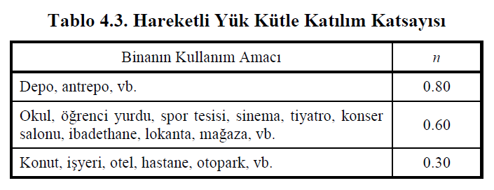
Where G is a constant load impact, snow load effect S, M d (Z) is 4.4.3 shows' e which is determined by the vertical seismic effects. The effective live load effect is calculated as Q e = nQ using the Live Load Mass Participation Coefficient n defined in TBDY Table 4.3 . E d (H) shows the horizontal earthquake effect.
In the first (i = 1) step of the analysis, modal analysis is performed to the system by using internal forces and deformations obtained as a result of nonlinear incremental static calculations under static vertical loads . As a result of the modal analysis, period (T n ) and mode shape Φ n are revealed for each nth vibration mode .
The structural characteristics for the given (X) earthquake direction are as follows, as shown in TBDY Equation 4B.1 . The structure characteristics are expressed as the modal additive factor Γ xn (i) and Φ n (i) for the nth vibration mode for the earthquake direction (X) . Since the value of Γ n (X) shown in TBDY Equation 4B.1 is calculated in each push step in the ARSA method, it is expressed with the term Γ xn (i) . Here (i) shows the number of steps.
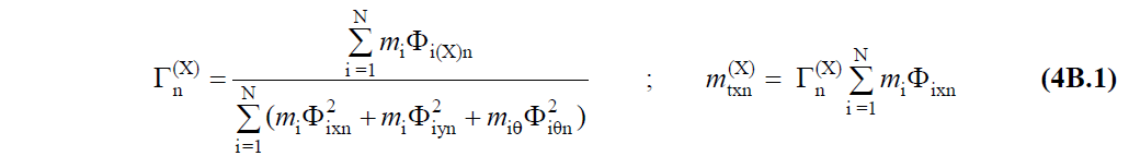
As shown in TBDY Equation 4B.1 , Φ i (X) n means the nth natural vibration mode shape amplitude in the earthquake direction at the i'th storey (X). However, in the finite element solution, since the masses meet at the nodes, here Φ i (X) can be thought of as the i'th joint point amplitude. In this case m i is the total mass of the i th joint.
In the other (i = 2,3…) steps of the analysis, plastic hinges are defined and a modal analysis is made to the system by using the internal forces, deformations and stiffness matrix of the structure at the end of that step. As a result of the modal analysis, period (T n ) and mode shape Φ n are revealed for each nth vibration mode .
Consequently, the structure characteristics are yn (i) and Φ yn for earthquake direction Γ xn (i) and Φ xn (i) and (Y) for earthquake direction (X) in the i'th step of the thrust analysis for each n'th mode. (i) It is found by performing modal analysis.