
How does ideCAD design joining plate connection according to AISC 360-16?
-
Joining plate connection limit states and geometry checks are done automatically according to AISC 360-16.
Symbols
Ab: Non-threaded bolt web characteristic cross-sectional area
Ag: Gross area
An: Net cross-section area
d: Characteristic diameter of the stem of the bolt (the diameter of the non-threaded stem of the bolt)
dh: Bolt hole diameter
Fy: Structural steel characteristic yield strength
Fu: Structural steel characteristic tensile strength
Fyb: Bolt characteristic yield strength
Fub: Bolt characteristic tensile strength
s: Distance between bolt-hole centers
Lc: The clear distance between bolt holes
Le: The distance from the center of the bolt hole to the edge of the assembled element
Leh: The horizontal distance from the center of the bolt hole to the edge of the assembled element
Lev: The vertical distance from the center of the bolt hole to the edge of the assembled element
tp: Plate thickness
Pt: Bolt tensile strength
Rn: Characteristic strength
w: Size of weld leg, in. (mm)
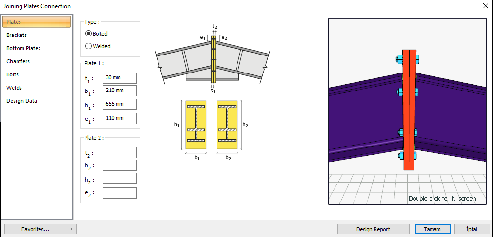
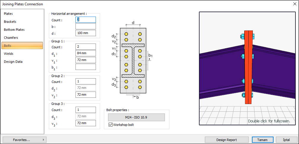
Connection Geometry
GEOMETRY CHECKS
Horizontal Edge Distance
The distance from the center of the hole to the edge of the connected part in the horizontal direction is checked per AISC 360-16.
|
Leh ≥ Le-min |
AISC 360-16 J3.4 |
|
|
|
Leh |
55 mm |
Leh ≥ 2d = 2 * 24 = 48 mm conformity check for application |
√ |
|
Le- min |
30 mm |
Minimum distance check according to Table J3.4 |
√ |
Vertical Edge Distance
The distance from the center of the hole to the edge of the connected part in the vertical direction is checked per AISC 360-16.
|
Lev ≥ Le-min |
AISC 360-16 J3.4 |
|
|
|
Lev |
51.519 mm |
L eh ≥ 2d = 2 * 24 = 48 mm conformity check for application |
√ |
|
Le-min |
32 mm |
Minimum distance check according to Table J3.4 |
√ |
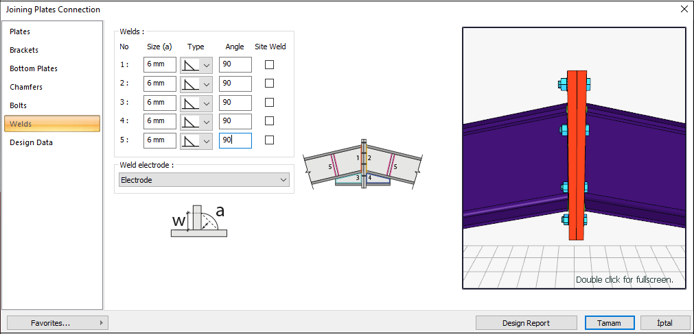
Weld Size
The minimum size of fillet welds is checked according to AISC 360-16 Table J2.4
|
w ≥ wmin |
AISC 360-16 J2.4 |
|
|
|
w |
8.487 mm |
|
√ |
|
wmin |
5 mm |
Table J2.4 |
√ |
STRENGTH CHECKS
Bolt Tension at Support
Bolt tensile strength is checked due to axial force and bending moment interaction effect.
|
Ft |
750000 kN/m2 |
|
|
Ab |
|
AISC DG-4-2nd 3.7 |
|
Pt |
|
|
|
h0 |
473.038 mm |
|
|
h1 |
315.271 mm |
|
|
dm |
394.154 mm |
|
|
Mreq |
119.655 kNm |
|
|
Nreq |
-27.504 kN |
|
|
Rreq |
|
|
|
Rn |
|
|
|
ΦRn |
|
|
|
Required |
Available |
Ratio |
Control |
|---|---|---|---|
|
289.822 kN |
1017.876 kN |
0.285 |
√ |
End Plate Thickness
The required end plate thickness, tp, for four bolts stiffened end plate connection is checked according to AISC 358-16 §6.8
|
Ab |
|
|
|
Pt |
|
|
|
Mn |
|
AISC 358-16 (6.8-5) |
|
Fyp |
235000 kN/m2 |
|
|
Yp |
2517.347 mm |
|
|
tp |
|
|
|
Required |
Available |
Ratio |
Control |
|---|---|---|---|
|
28.921 mm |
30 mm |
0.964 |
√ |
End Plate Shear Yield
The shear strength of connecting elements in shear is the minimum value obtained according to the limit states of shear yielding and shear rupture. Shear yielding is checked according to AISC 360-16.
|
Fyp |
235000 kN/m2 |
|
|
Ag |
|
AISC 360-16 J4-3 |
|
dm |
394.154 mm |
|
|
Mreq |
119.655 kNm |
|
|
Nreq |
-27.504 kN |
|
|
Rreq |
|
|
|
Rn |
|
|
|
ΦRn |
|
|
|
Required |
Available |
Ratio |
Control |
|---|---|---|---|
|
289.822 kN |
1776.6 kN |
0.163 |
√ |
End Plate Shear Rupture
The shear strength of connecting elements in shear is the minimum value obtained according to the limit states of shear yielding and shear rupture. Shear rupture is checked according to AISC 360-16.
|
Fu |
360000 kN/m2 |
|
|
An |
|
AISC 360-16 J4-4 |
|
dm |
394.154 mm |
|
|
Mreq |
119.655 kNm |
|
|
Nreq |
-27.504 kN |
|
|
Rreq |
|
|
|
Rn |
|
|
|
ΦRn |
|
|
|
Required |
Available |
Ratio |
Control |
|---|---|---|---|
|
289.822 kN |
1477.44 kN |
0.196 |
√ |
Bolt Shear at Support
The calculation is made using the Elastic method, one of the methods selected in the steel analysis settings tab. For the details of this check, AISC Manual 14th 7-8 is used as a reference. In this check, the operation is performed on half of the symmetry axis and is calculated to form a force pair with the required force.
|
Ab |
|
|
|
Fnv |
|
|
|
Rn |
|
AISC 360-16 J3-1 |
|
ΦRn |
|
|
|
Required |
Available |
Ratio |
Control |
|---|---|---|---|
|
5.313 kN |
610,725 kN |
0.009 |
√ |
Bolt Bearing on End Plate
Bearing strength limit states of the connection plate that are “shear tear out” and “ovalization of bolt hole” for both end and inner bolts are checked according to AISC 360-16.
|
dh |
24+3=27 mm |
|
|
Lc,edge |
|
|
|
Rn |
|
AISC 360-16 J3-6a |
|
Rn-edge |
|
|
|
Lc,spacing |
|
|
|
Rn-spacing |
|
|
|
Rn |
|
|
|
ΦRn |
|
|
|
Required |
Available |
Ratio |
Control |
|---|---|---|---|
|
5.313 kN |
1672.2kN |
0.003 |
√ |
Weld Size
The required end weld size is checked according to AISC DG-4.
|
Fyp |
235000 kN/m2 |
AISC DG-4-2 nd 2.1.7 |
|
tbw |
9 mm |
|
|
Fe |
480000 kN/m2 |
|
|
w |
|
|
|
Required |
Available |
Ratio |
Control |
|---|---|---|---|
|
3.97 mm |
8.487 mm |
0.468 |
√ |
Weld Strength
The required end weld strength is checked according to AISC DG-4.
|
w |
8.487 mm |
|
|
FE |
480 N/mm2 |
|
|
le |
190.193 mm |
|
|
Rn |
|
AISC DG-4-2 nd 2.1.8 |
|
ΦRn |
|
|
|
Required |
Available |
Ratio |
Control |
|---|---|---|---|
|
5.313 kN |
492.981 kN |
0.011 |
√ |
Next Topic