
In rigid diaphragm structures, the rigid center is calculated by the method defined by the formulas below.
Xr= ∑ Vy(i)* X(i) ) / ∑Vy(i)
Y r = ∑ Vx (i) * Y (i) ) / ∑V x (i)
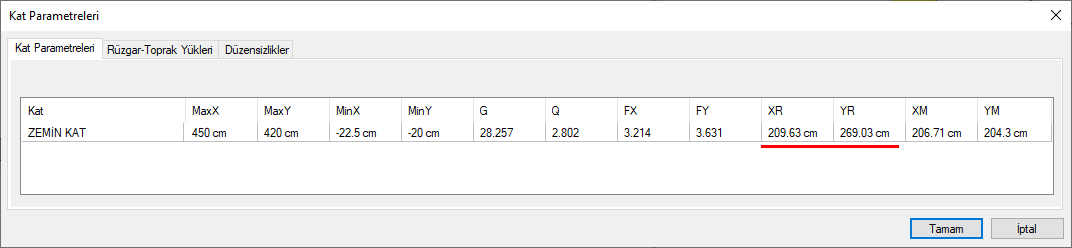
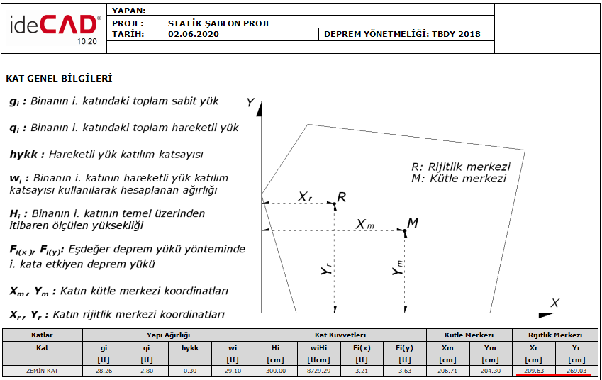
In the program, the coordinates of the rigid center are given in the Floor parameters dialog and under the Floor General Information title in the report.
Xr = The perpendicular distance of the center of rigidity of the floor to the Y axis.
Yr = The perpendicular distance of the center of rigidity of the floor to the X axis.
Vy i = Y direction i. is the shear force of the column calculated from additional non-eccentric loading.
X (i) = i. is the perpendicular distance of the center of gravity of the column to the Y axis.
Vx i = X direction i. is the shear force of the column calculated from additional non-eccentric loading.
Y (i) = i. is the perpendicular distance of the center of gravity of the column to the X axis.
Download ideCAD for Structural Engineering
The center of stiffness values calculated by the program will be verified manually using the formulas given above.
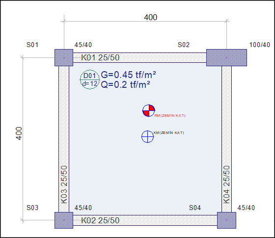
Typical floor plan and dimensions:
Analysis of the structure is made by giving the ratio of the analysis settings to the eccentric as zero.
Yr account
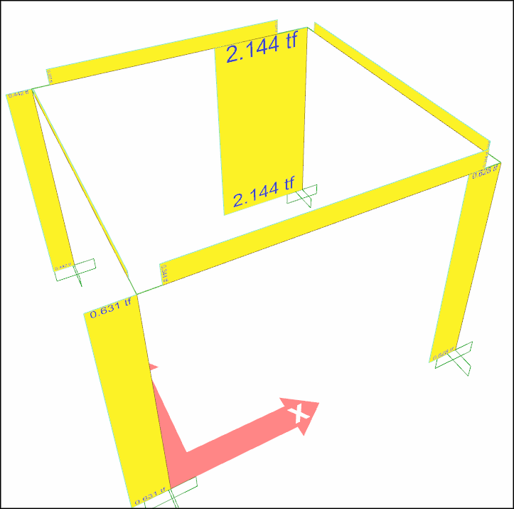
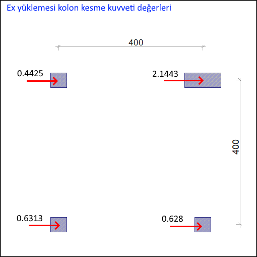
The shear forces calculated in the columns at Ex loading are shown below.
Y r = ∑ Vx (i) * Y (i) ) / ∑V x (i)
Yr = (0.4225 * 400 + 2.1443 * 400 + 0.6313 * 0 + 0.628 * 0) / (0.4225 + 2.1443 + 0.6313 + 0.628)
Yr = 269.03 cm
Xr account
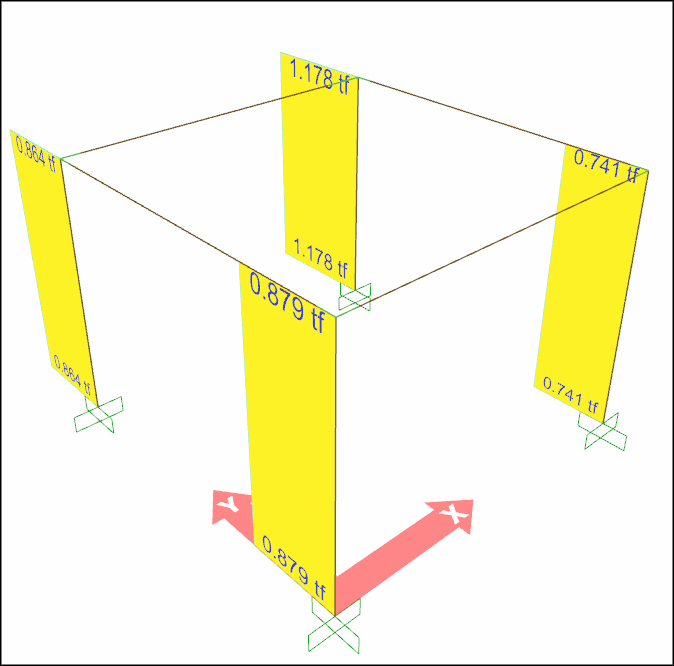
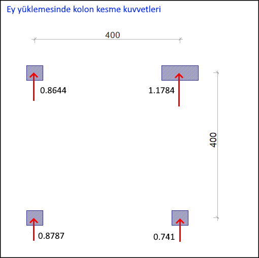
The shear forces calculated in columns at O loading are shown below.
Xr = ∑ Vy(i)* X(i) ) / ∑Vy(i)
Xr = (0.8644*0 + 0.8787*0 + 1.1784*400 + 0.741*400) / (0.8644+0.8787+1.1784+0.741)
Xr = 209.63 cm
The values that appear in the Floor Parameters in the program:
The values that appear in the Floor General Information report header in the program:
Download ideCAD for Structural Engineering
Next Topic
Related Topics