
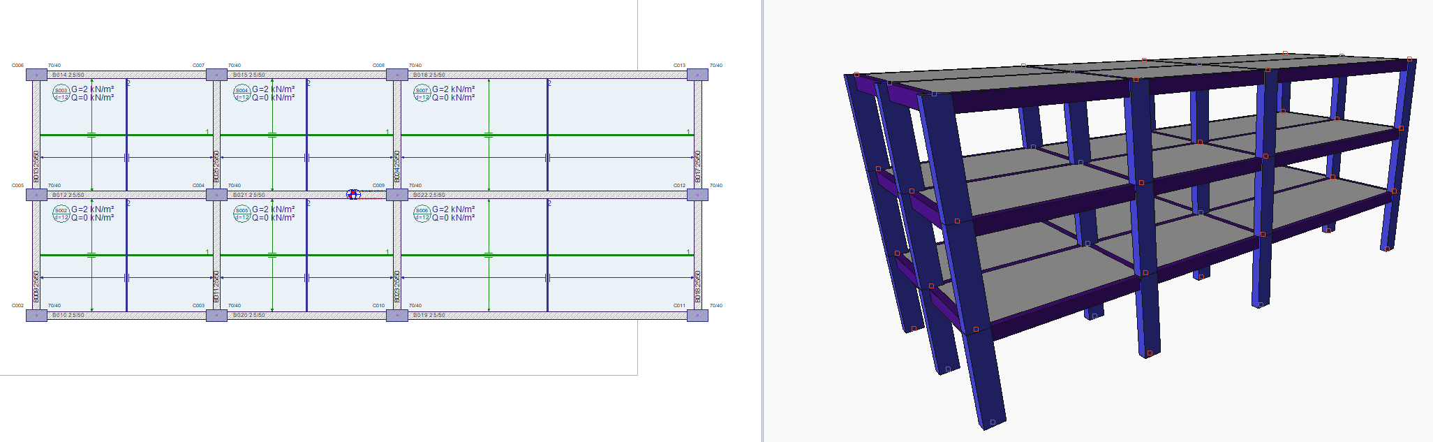
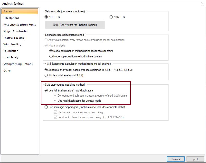
The reinforced concrete structure, on which you can see the plan and 3d view above, consists of 2 openings of 6 m and 10 m in the X direction, while it has 2 4 m openings in the Y direction. Earthquake effects will be determined by solving the structure modeled as reinforced concrete moment transferring frame and full rigid diaphragm with dynamic (modal) analysis in accordance with the dynamic eccentricity method and mode combination method. Comparative model and result review with ETABS is below.
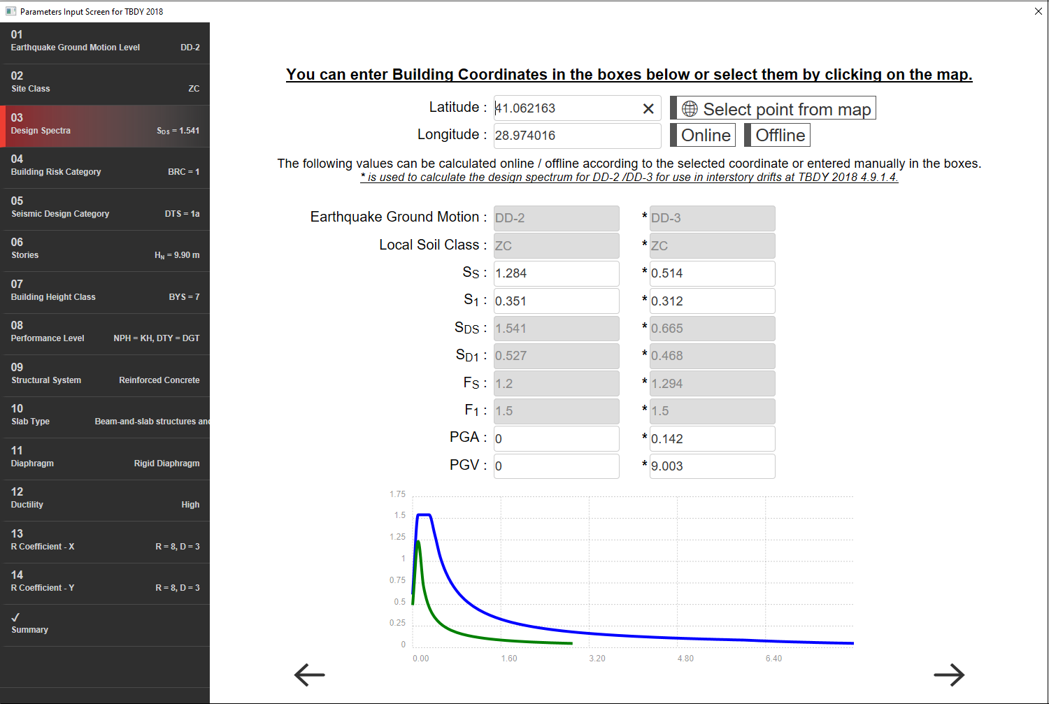
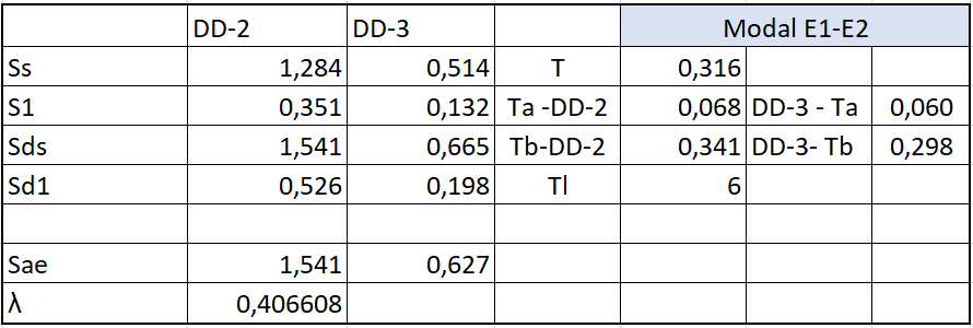
The structure's latitude and longitude and soil parameters for TBDY 2018, elastic spectrum values and BYS, BKS, DTS etc. classification is indicated in the image below. C30 S420 material was used for frame elements and C20 S420 material was used for flooring.
Project data: Solutions are implemented with ETABS v17 and ideCAD Static v10.91.
0173_6_slab_3_story_NORMLA.ide103kat_13.11.2018-asıl sepktra.EDB
SOLUTION:
1- Modeling Steps
a- For material definitions, unit volume weight and concrete characteristic compressive strength must be entered the same in both programs.
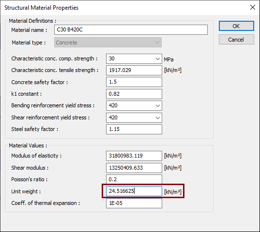
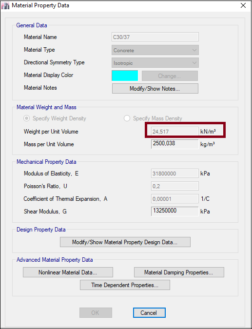
-
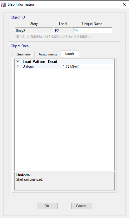
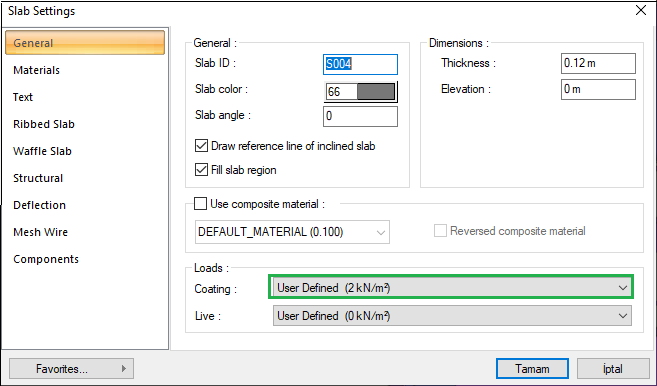
Unit volume weight has been entered as 0 for the flooring material and added as the area distributed load on the floor during loading in the model.
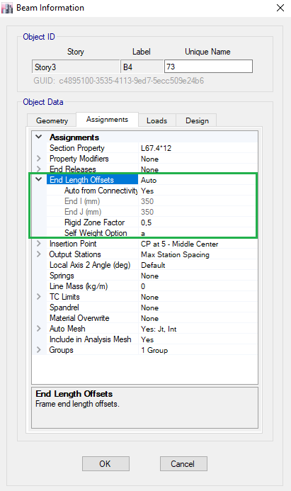
b- The point to be considered for cross section definition; ideCAD uses static table beam section for fully rigid diaphragm selection. This situation should also be created with ETABS. Effective section stiffness factors must be entered.
-
Section definition for reinforced concrete column should be made with ETABS as follows:
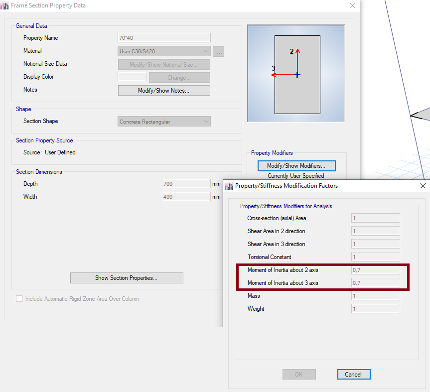
Effective section stiffness multipliers are automatically generated with ideCAD Statik . In the optional report, the values used on the basis of elements are reported.
-
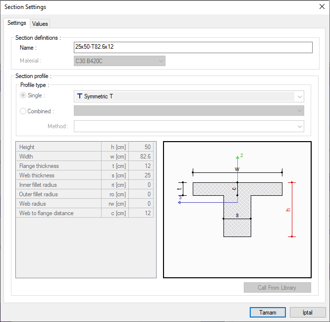
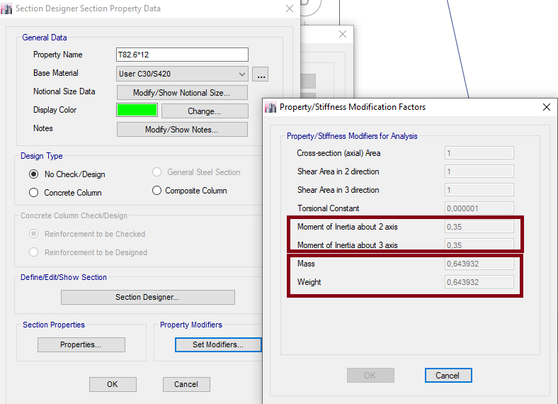
In ETABS, since ideCAD calculates beams with a table cross section in the use of a fully rigid diaphragm, a table section should be entered in ETABS. ETABS uses the axle spacing you entered in the weight calculation of slabs, which causes the weight of the screed section to be taken into account twice in the table section entry. In order to prevent this, the procedure described below should be applied for the table sections.
-
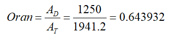
It should be entered with a reinforced concrete beam table and the ratio of the table parts in ETABS should be written as in the following image in order to make the mass calculation the same between the two programs. When calculating the ratio , the area of the rectangular cross section / the area of the table section is used.
-
For example, for the T section you see in the image, this calculation is made as follows:
Tabbed cross section area:
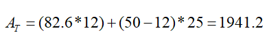
Rectangular cross-sectional area:
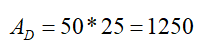
-Rate:
-
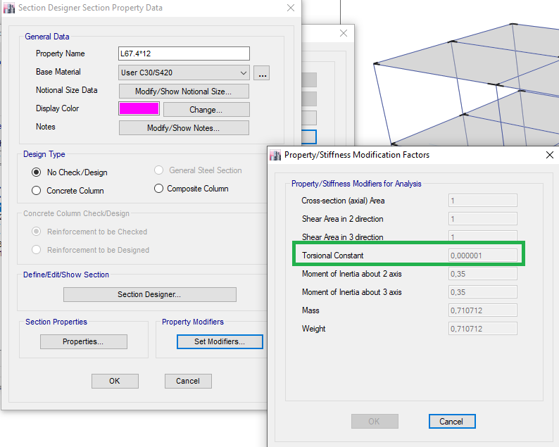
Another point to note is that if the suitability for beams is marked in ideCAD Static, the 'torsional constant' section, which you can see in the following image in the set modifiers section of ETABS , should be intervened. 10 (-6) should be written.
-
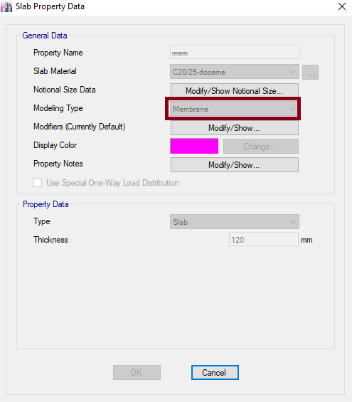
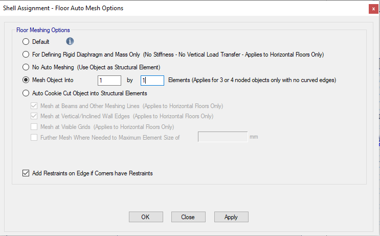
As a full rigid diaphragm will be used for flooring, membrane entry should be made with ETABS.
2- Additional Regulations for Determination of Building Mass
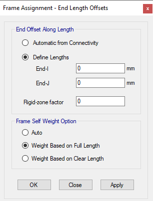
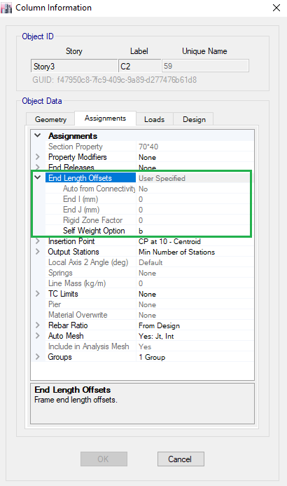
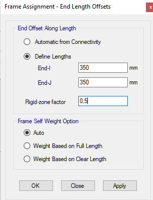
a- For reinforced concrete column
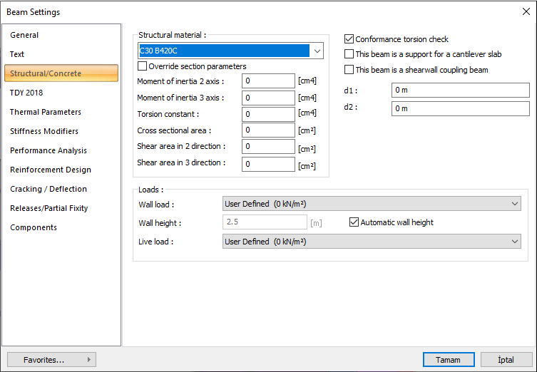
b- For reinforced concrete beam
c- For flooring, ideCAD performs static loading over the clean opening. For this reason, the loads written on the ideCAD Static laying menu should be calculated over the clean area and entered by decreasing the ratio between the two areas, as ETABS calculates the full area. In summary, etabs (clear area / full area) * should be loaded.
-
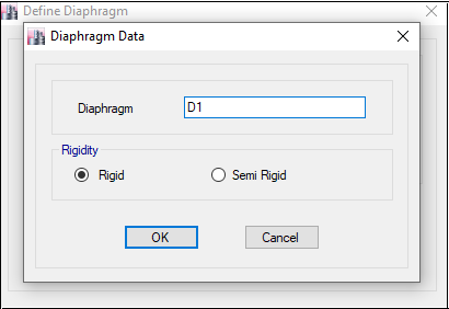
Diaphragm Definition
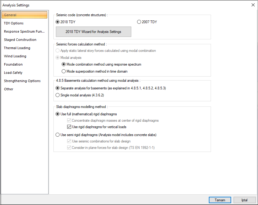
3- Modal Analysis Settings and Settings for Earthquake Effects
-
In ideCAD Static, two load case analysis type should be selected. In this type, the additional eccentricity effect is solved by the dynamic method. For the dynamic method, ETABS modeling should be searched from etabs sources with the title 'accidental torsion with dynamic procedure'.
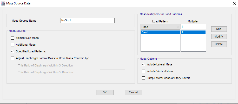
1- Mass source regulation
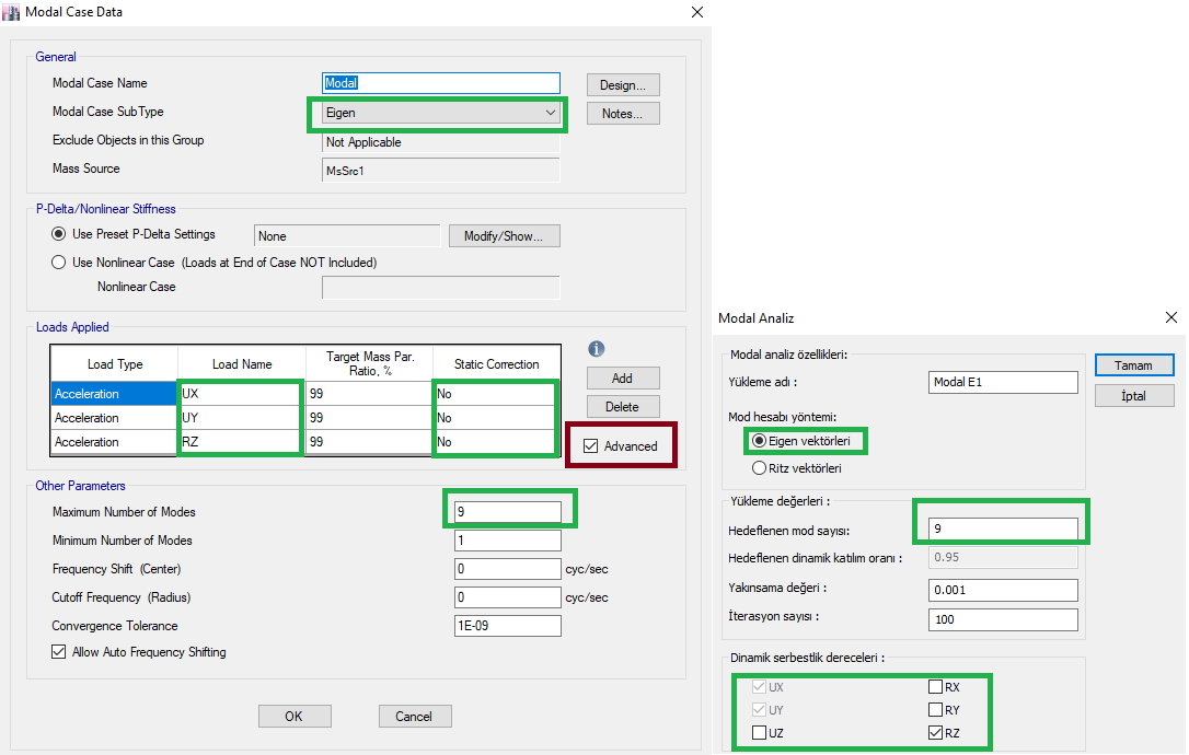
2- Modal case editing
Note: The interface tab on the left belongs to ideCAD Static. In ETABS, static correction tab should remain as 'No'. If your mode number does not provide enough mass participation rate, ideCAD Static does not go to an application with the mode results at hand to provide an approximate method. However, if this section is set as 'Yes' in ETABS, editing is done with an approximate method. You can review the etabs manual for details.
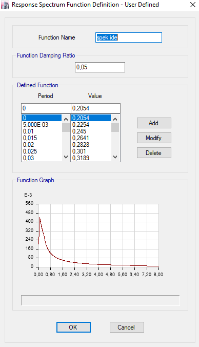
3- Defining the spectrum function
Run ideCAD as static administrator. Analyze the project once. Type exportspectrum to the command line in the lower toolbar . Go to the program files - ideCAD v10 folder located in the c folder on your computer. You will see a txt file named exp_spec.txt, check out this file. ideCAD works with dot for decimals, ETABS is comma or dot whichever is set on your computer, edit the txt file accordingly. Then import the file named exp_spec while ETABS - Functions -User Defined is selected.
Design Spectrum Reduced by Respose Modification (4.4.1)
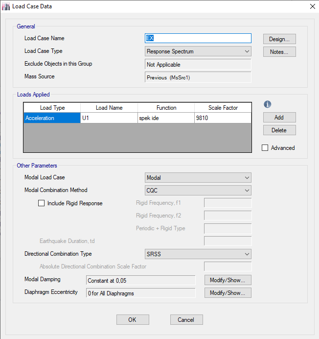
4- Loading Cases
Load Combinations of Earthquake Effects for Perpendicular Directions (4.4.2.1)
2- Analysis Results
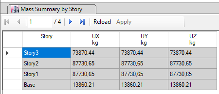
a) Structure Weight
-
Floor based
ideCAD Structural
ETABS
-
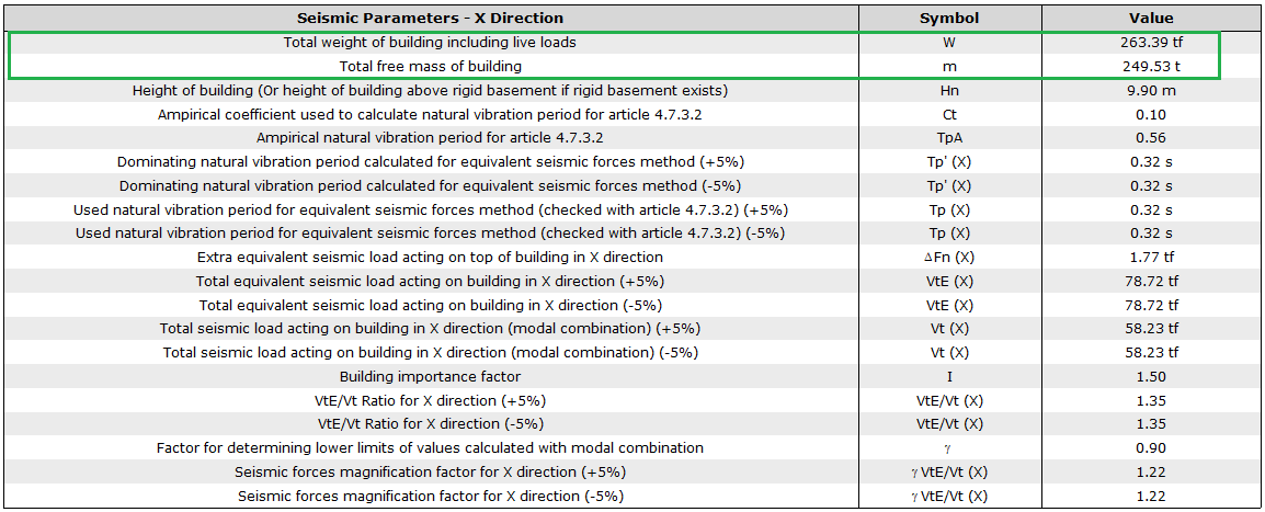
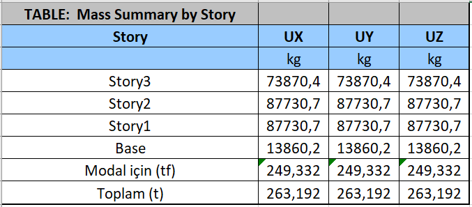
Total
ideCAD Structural
ETABS
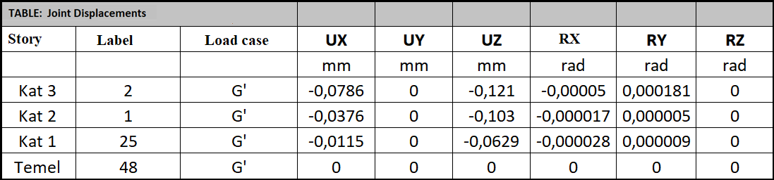
b) Vertical Results
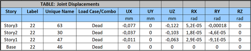
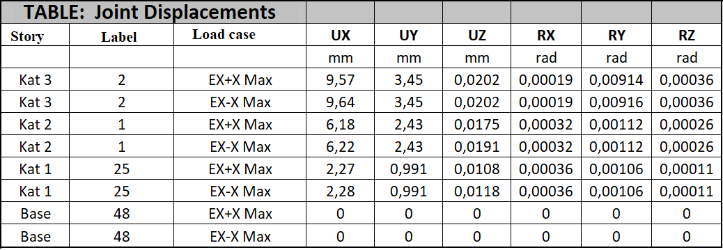
1- Displacement
In the ideCAD model, starting from the top floor located between the column C0013 and the beam B016-B017, the joint point values named N2 - N1 - N25 - N48 were read sequentially.
ideCAD Structural
ETABS
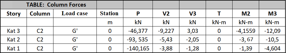
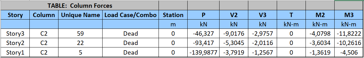
2- Frame Results
ideCAD Structural
C0002 corner column
ETABS
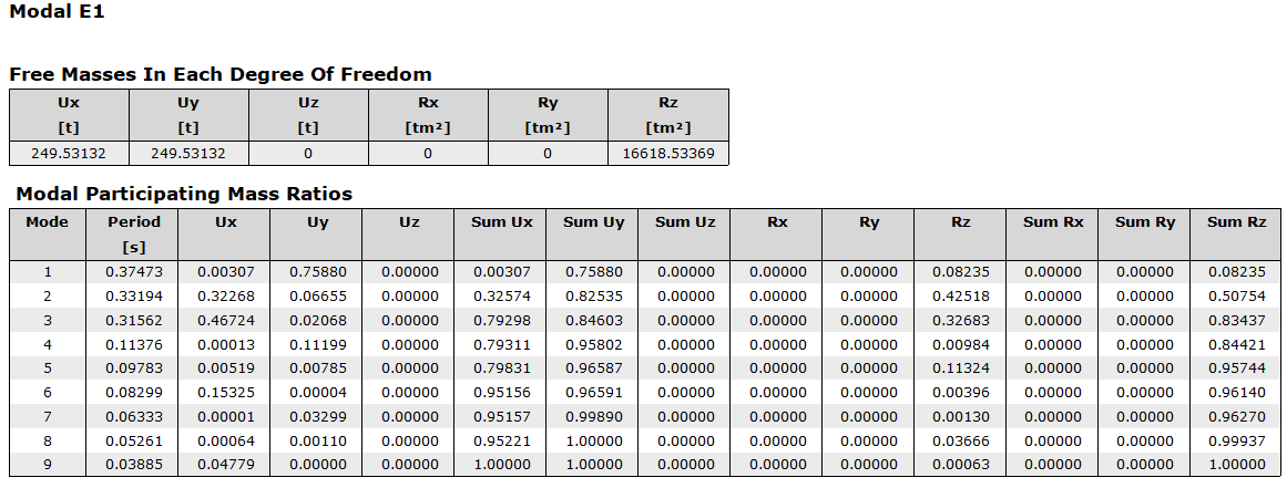
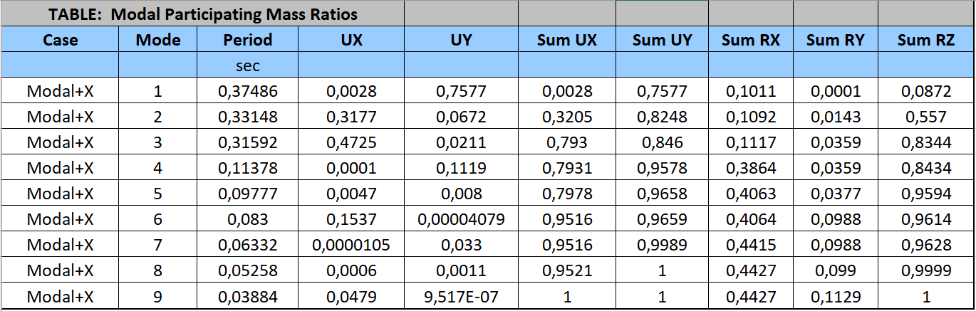
c) Modal Analysis
ideCAD Structural
ETABS
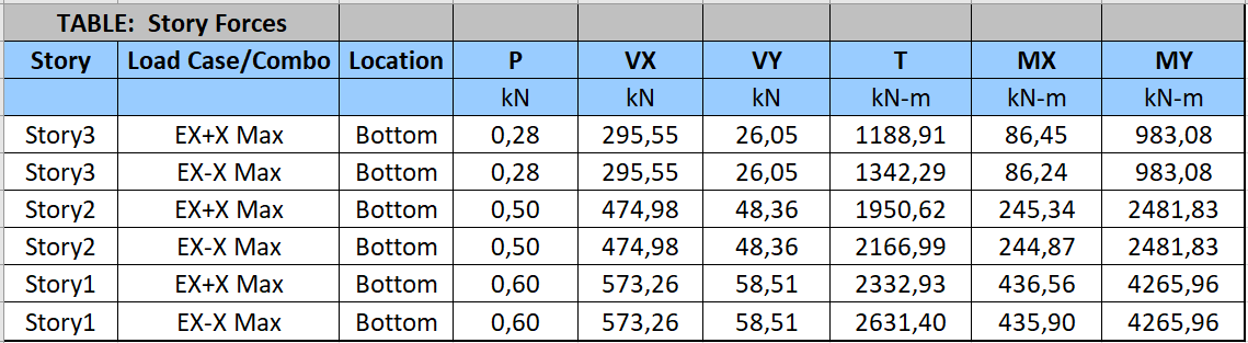
d) Horizontal Earthquake Load Results
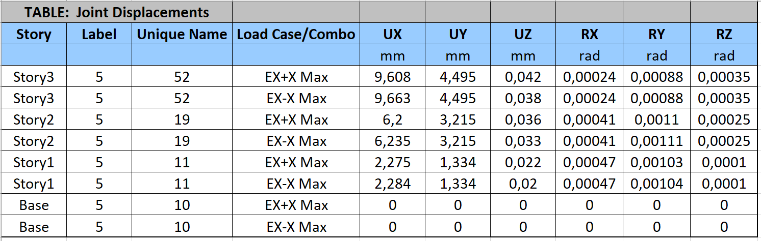
1- Displacement
ideCAD Structural
ETABS
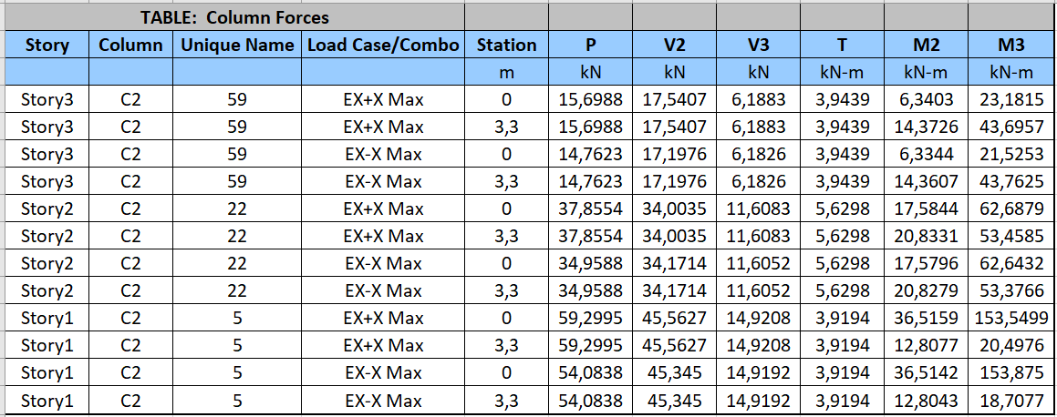
2- Frame Results
ideCAD Structural
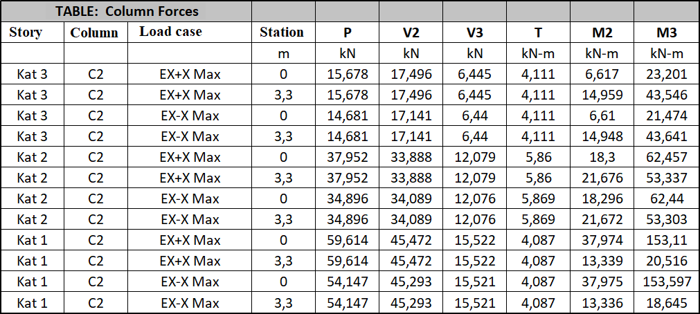
ETABS
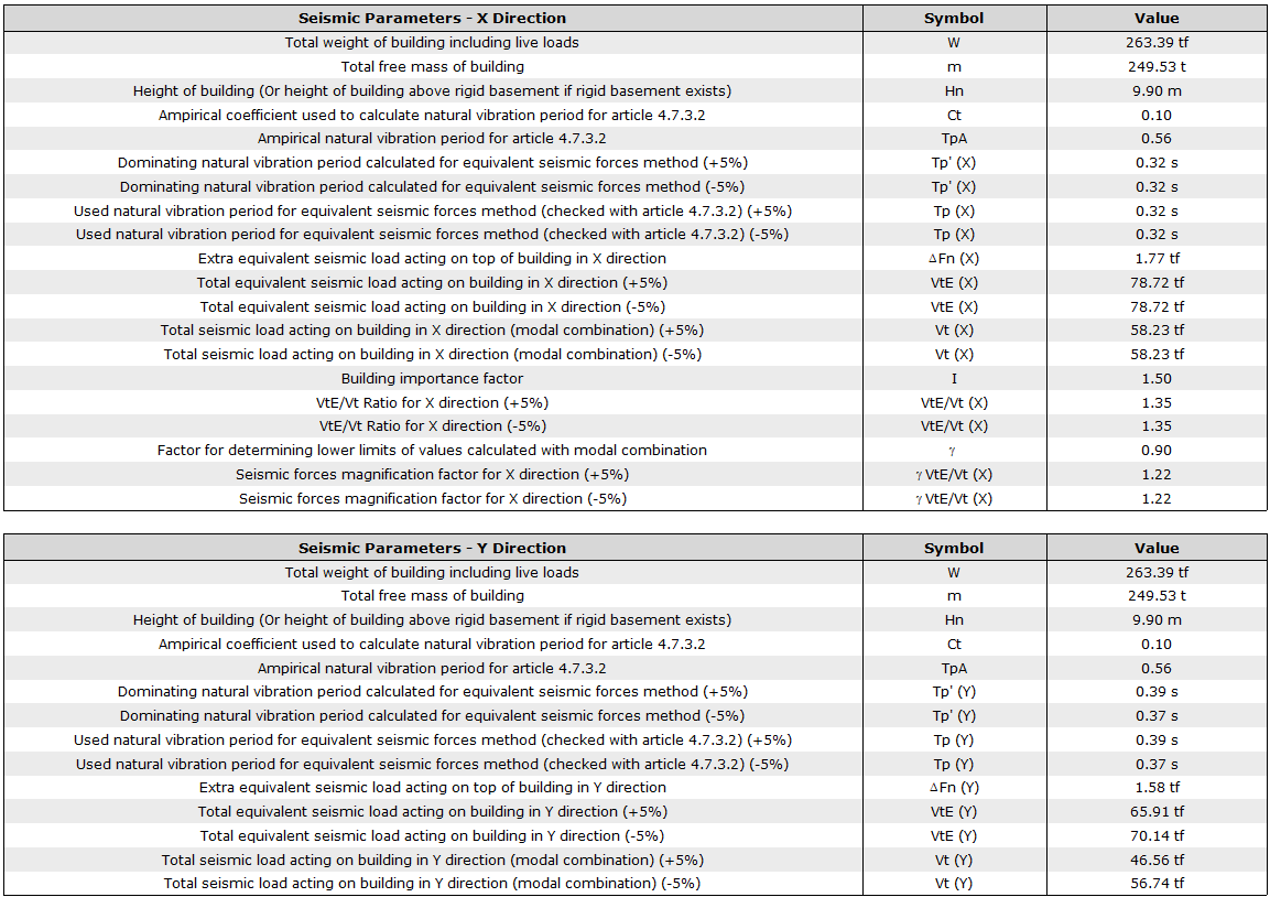
e) Calculation of Magnification Coefficient According to Equivalent Earthquake Load Method
Equivalent Lateral Force Method Seismic Response Coefficient for Equivalent Lateral Force Method per ASCE 7-16 with ideCAD
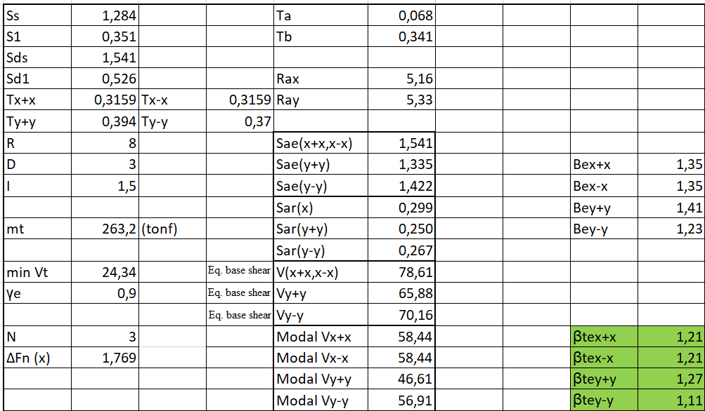
The information used in the account in the ideCAD Static Dynamic analysis report is summarized below.
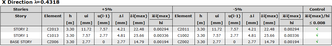
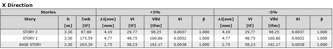
f) Relative Story Drifts Calculation
Calculation and Control of Relative Story Displacements.
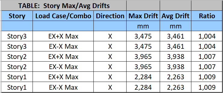
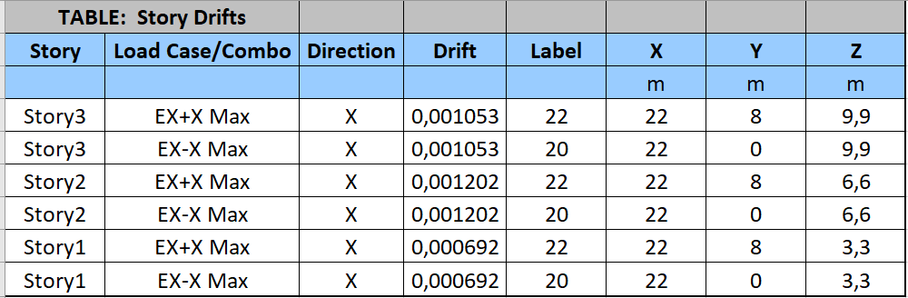
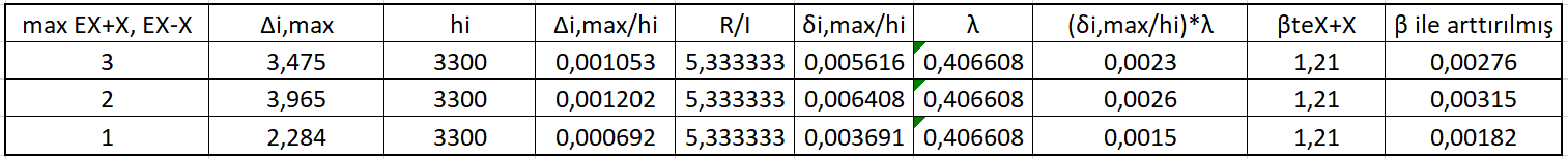
The calculation made in the relative storey displacement section of the ideCAD Structural Seismic regulation report is below.
g) Second Order Effect Calculation
P-Delta Effects per ASCE 7-16 with ideCAD section contains the philosophy of the account and how it is done. This account cannot be obtained directly from ETABS. The required data is taken from ETABS and the calculation is made manually.
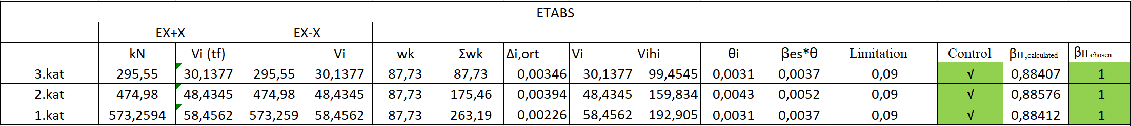
Calculation results are given in the second order effects section of the ideCAD Static Earthquake regulation report.
Next Topic