
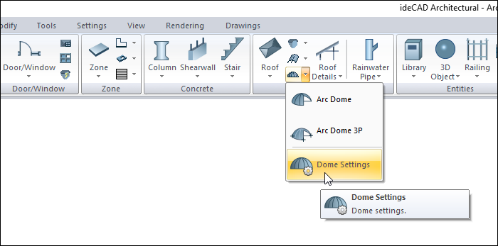
With the Dome Settings command, settings such as dome width, height, elevation, segment count, drawing, material selection, structural material can be accessed.
Location of Dome Settings Dialog
The Dome, which appears after the dome command is run, is also available in the auxiliary toolbar.
In the Architectural Program
You can access under the ribbon menu Home tab, Roof title.
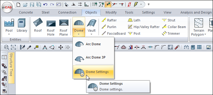
In Structural Program
You can access under the ribbon menu, Objects tab, Roof title.
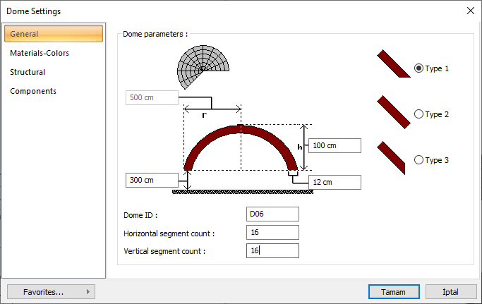
General Tab
|
Specifications |
|---|
|
Dome ID The dome name is entered. |
|
Horizontal segment count It determines how many horizontal parts (rings) the dome will be formed from. The more the number of pieces, the more rounded the dome lines are. |
|
Vertical segment count It determines how many vertical parts (slices) the dome will be formed from. The more the number of pieces, the more rounded the dome lines are. |
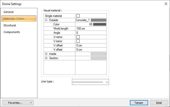
Materials-Colors Tab
|
Specifications |
|---|
|
Visual material 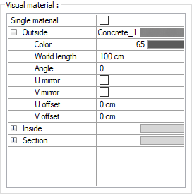
The material to be used on the surfaces of the dome is selected from the list. Surfaces are covered with the selected material and displayed as such in renderings. Texture length is entered into the world length. For example; If 1 is entered, the selected material texture is taken as 1 meter and covered on the relevant walls. In the angle, the angle of the texture is entered. Touch the U and V offset. The motion value in the x and y plane is entered. With U and V mirroring, the texture is symmetrical with respect to the y and x planes. By selecting the single material option, the material selected in "Outside material" is used on all surfaces of the dome |
|
Line type The line type of the line forming the dome is selected in the plan. Clicking the down arrow buttons to the right of the boxes opens the list of line types. From this list, the desired line type is selected by clicking with the left mouse button. |
Structural Tab
|
Specifications |
|---|
|
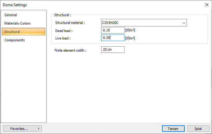
Structural material Select the static material to be used in the dome element from the list. Static material can be defined as a reinforced concrete element under Materials in Building Tree. |
|
Dead load Fixed external loads are entered, except for the reinforced concrete weight of the dome, which consists of thickness. |
|
Live load The moving load value to be used in the calculation of the dome is entered. |
|
Finite element width Enter the maximum finite element width to be taken as basis in shell calculation. The program analyzes shells by dividing them into trapezoidal form finite elements. Finite element width is automatically adjusted according to the shell shape, provided that it does not exceed the value entered in this row. |
Components Tab
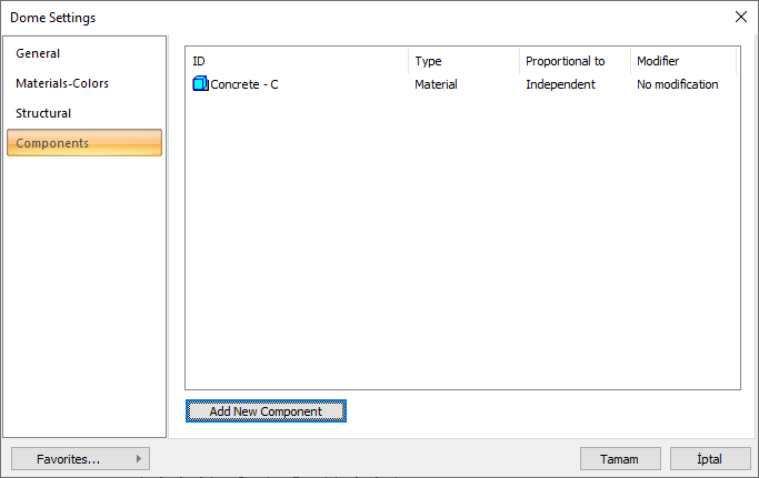
Add Building Components : Assigns the building materials defined for detailed building components metrics to the object.
-
Click on the building components button.
-
The Component Selection dialog will open.
-
In this dialog, click on the folder related to the material from the list on the left. Click on the material you want to use.
-
Set the parameters on the right.
-
Click the OK button. The "Component Selection" dialog will be closed. A summary line of the material will appear in the Building Components tab. More than one material assignment can be made to an object.
The parameters available in the component selection dialog are:
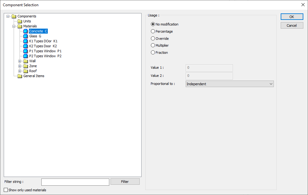
In the usage section
No modification: The amount of material to be assigned for the object in question is marked when it is desired to be used in the size that was previously specified in the material definition.
Percentage: This line is marked when it is desired to be used with the percentage of the amount previously determined in the material definition, as much as the value entered in the "Value 1" line in the same dialog. For example, if the material quantity is 70, if the line “Value 1” says 40, it means the material amount will be used up to 40 * 70%.
Override: This line is marked so that the quantity entered in the “Value 1” line in the same dialog will be used instead of the quantity previously determined in the material definition.
Multiplier: This line is marked in order to use the value found at the end of the multiplication of the value entered in the "Value 1" line in the same dialog with the amount previously determined in the material definition.
Fraction: This line is marked so that the amount determined in the material definition before will be used as the fraction value created by the values entered in the "Value 1" and "Value 2" lines in the same dialog. "Value 1" is the denominator "Value 2" is the denominator.
Proportional to: It is determined to what scale-area, circumference, length etc.-, region-side area, top, edge etc.- the material will be proportioned to. The content of the proportional list box is automatically determined according to the object and the size of the material. For example, a different list will be created if an operation is made for the column, a different list will be created for the library, a different list for the volume, and a different list for the field.
Next Topic