The design of steel truss elements subject to axial tension is explained in detail under this title according to AISC 360-16.
Symbols
Ag : Cross-section area without loss
Ae : Effective net cross-sectional area
An : Net cross-section area
Agv : Area without loss under shear stress
Anv : Net area under shear stress
Ant : Net area under tensile stress
Fy : Structural steel characteristic yield stress
Fu : Structural steel characteristic tensile strength
K : Twisting length coefficient
L: Element length between supported points
i: Radius of inertia
U: Stress irregularity effect coefficient
Ubs : A coefficient considering the spread of tensile stresses
Tn : Design tensile strength
Tensile Strength of Elements
-
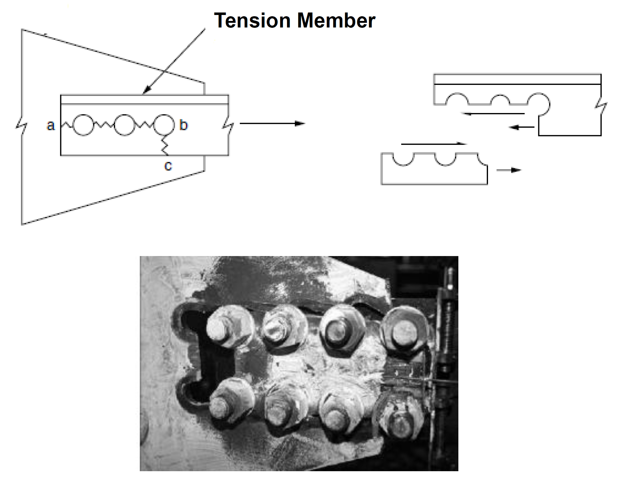
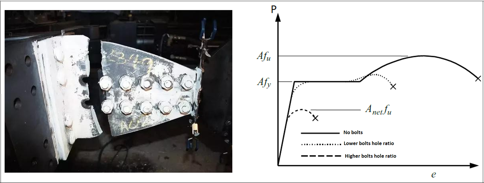
Tension members are structural elements that transmit the axial tensile forces. If tension elements are used together with bolted joints, yield stress will be reached earlier in the areas where bolt holes are located. This situation will affect the strength determined by using the load-displacement curve.
-
In bolted and welded joints of tension members, the cross-sectional area operating in load transfer is not equal to the entire cross-section area due to the uneven distribution of the load.
-
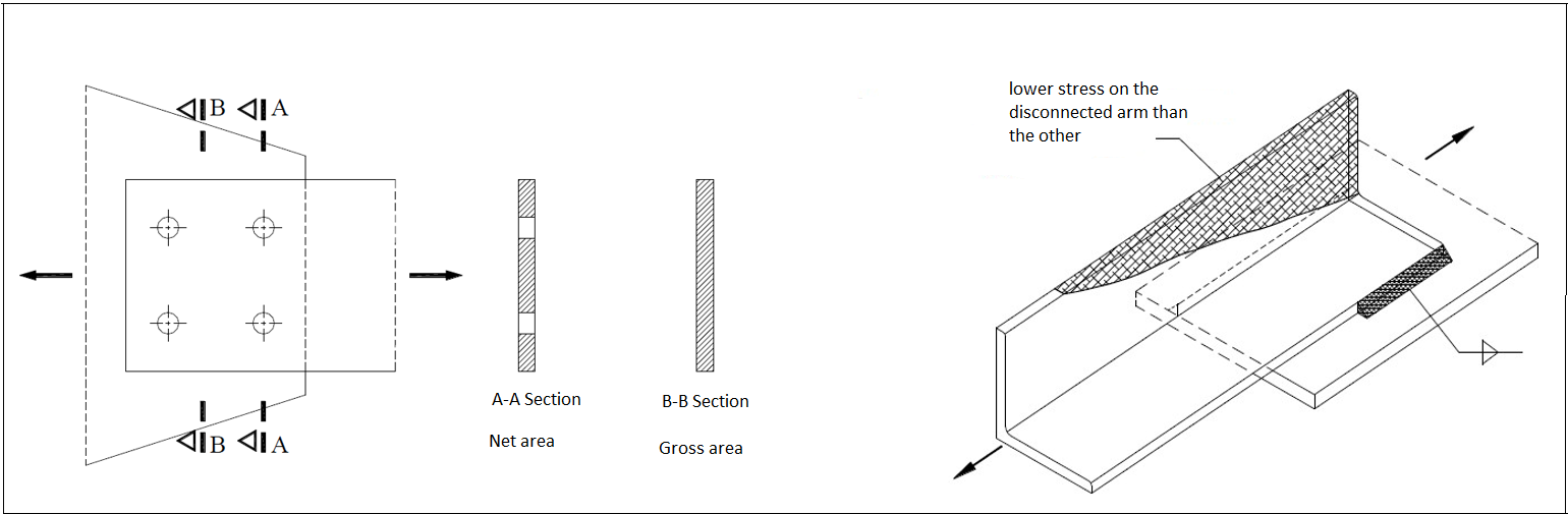
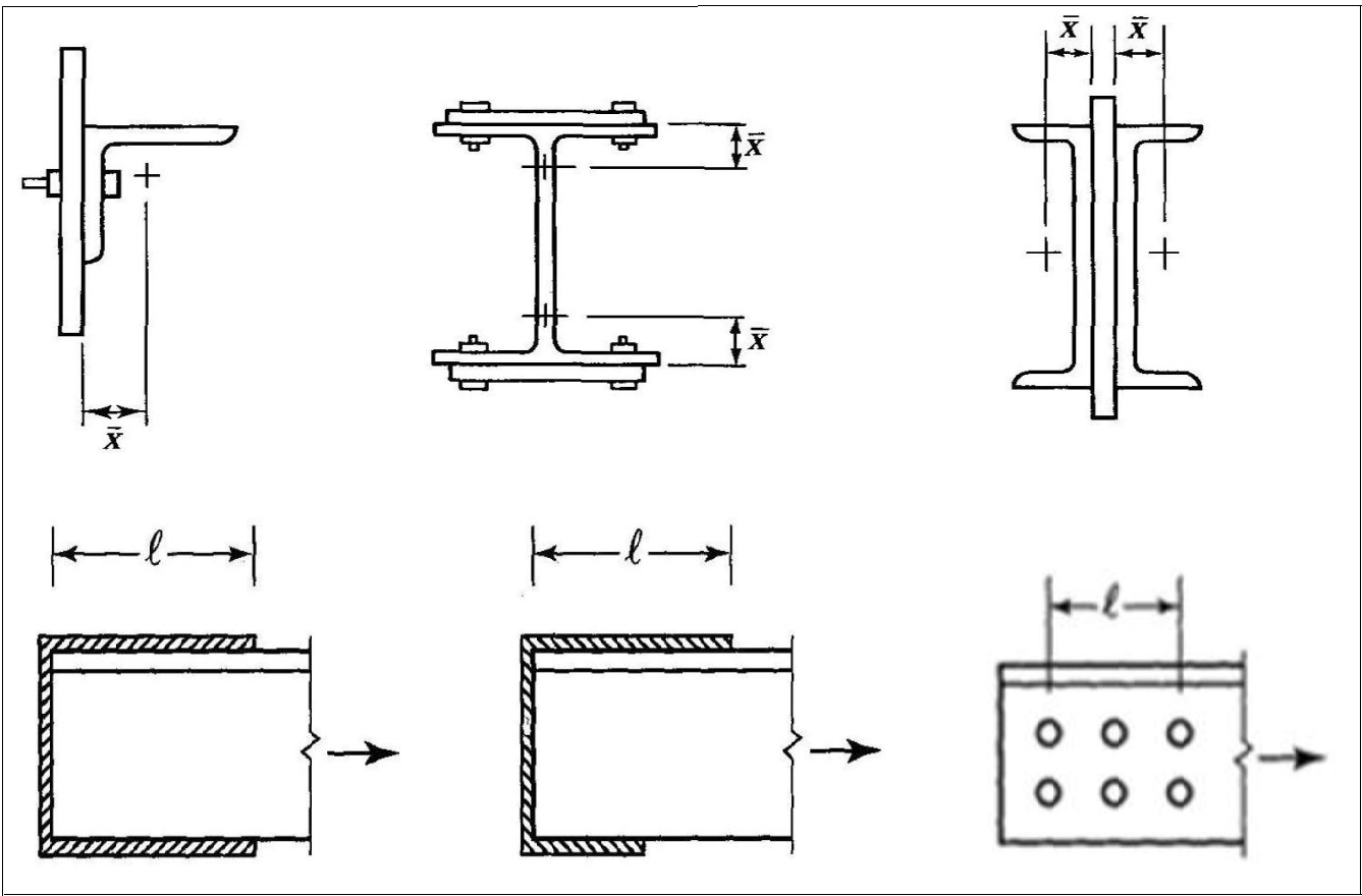
Since the L and U sections are used, especially in the corners not connected with bolts or welds, a certain region is called an effective area in load distribution. The consequence of this partial connection is that the connected element becomes overloaded, and the unconnected part is not fully stressed. Due to this phenomenon called the 'Shear Lag' effect, an effective net area is used in the design.
-
Three different areas are used in the strength calculation of tension members:
-
Gross Area (Ag)
-
Net Area (An)
-
Effective Net Area (Ae)
-
'%3e%3cg transform='translate(167%2c0)'%3e%3cg transform='translate(-13%2c0)'%3e%3cg transform='translate(0%2c-3)'%3e%3cuse xlink:href='%23MJMATHI-41' x='0' y='0'%3e%3c/use%3e%3cuse transform='scale(0.707)' xlink:href='%23MJMATHI-6E' x='1061' y='-213'%3e%3c/use%3e%3cuse xlink:href='%23MJMAIN-3D' x='1552' y='0'%3e%3c/use%3e%3cg transform='translate(2609%2c0)'%3e%3cuse xlink:href='%23MJMATHI-41' x='0' y='0'%3e%3c/use%3e%3cuse transform='scale(0.707)' xlink:href='%23MJMATHI-67' x='1061' y='-213'%3e%3c/use%3e%3c/g%3e%3cuse xlink:href='%23MJMAIN-2212' x='4021' y='0'%3e%3c/use%3e%3cuse xlink:href='%23MJMATHI-6E' x='5022' y='0'%3e%3c/use%3e%3cuse xlink:href='%23MJMAIN-D7' x='5845' y='0'%3e%3c/use%3e%3cuse xlink:href='%23MJMAIN-28' x='6845' y='0'%3e%3c/use%3e%3cg transform='translate(7235%2c0)'%3e%3cuse xlink:href='%23MJMATHI-64' x='0' y='0'%3e%3c/use%3e%3cuse transform='scale(0.707)' xlink:href='%23MJMATHI-65' x='736' y='-213'%3e%3c/use%3e%3c/g%3e%3cuse xlink:href='%23MJMAIN-D7' x='8407' y='0'%3e%3c/use%3e%3cuse xlink:href='%23MJMATHI-74' x='9408' y='0'%3e%3c/use%3e%3cuse xlink:href='%23MJMAIN-29' x='9770' y='0'%3e%3c/use%3e%3c/g%3e%3c/g%3e%3c/g%3e%3c/g%3e%3c/svg%3e)
'%3e%3cg transform='translate(167%2c0)'%3e%3cg transform='translate(-13%2c0)'%3e%3cg transform='translate(0%2c-50)'%3e%3cuse xlink:href='%23MJMATHI-41' x='0' y='0'%3e%3c/use%3e%3cuse transform='scale(0.707)' xlink:href='%23MJMATHI-65' x='1061' y='-213'%3e%3c/use%3e%3cuse xlink:href='%23MJMAIN-3D' x='1458' y='0'%3e%3c/use%3e%3cg transform='translate(2514%2c0)'%3e%3cuse xlink:href='%23MJMATHI-41' x='0' y='0'%3e%3c/use%3e%3cuse transform='scale(0.707)' xlink:href='%23MJMATHI-6E' x='1061' y='-213'%3e%3c/use%3e%3c/g%3e%3cuse xlink:href='%23MJMAIN-D7' x='4011' y='0'%3e%3c/use%3e%3cuse xlink:href='%23MJMATHI-55' x='5012' y='0'%3e%3c/use%3e%3c/g%3e%3c/g%3e%3c/g%3e%3c/g%3e%3c/svg%3e)
'%3e%3cg transform='translate(167%2c0)'%3e%3cg transform='translate(-13%2c0)'%3e%3cg transform='translate(0%2c-29)'%3e%3cuse xlink:href='%23MJMATHI-55' x='0' y='0'%3e%3c/use%3e%3cuse xlink:href='%23MJMAIN-3D' x='1045' y='0'%3e%3c/use%3e%3cuse xlink:href='%23MJMAIN-31' x='2101' y='0'%3e%3c/use%3e%3cuse xlink:href='%23MJMAIN-2212' x='2824' y='0'%3e%3c/use%3e%3cg transform='translate(3825%2c0)'%3e%3cg transform='translate(120%2c0)'%3e%3crect stroke='none' width='692' height='60' x='0' y='220'%3e%3c/rect%3e%3cg transform='translate(60%2c676)'%3e%3cuse xlink:href='%23MJMATHI-78' x='0' y='0'%3e%3c/use%3e%3cuse xlink:href='%23MJMAIN-AF' x='63' y='-8'%3e%3c/use%3e%3c/g%3e%3cuse xlink:href='%23MJMATHI-6C' x='197' y='-690'%3e%3c/use%3e%3c/g%3e%3c/g%3e%3c/g%3e%3c/g%3e%3c/g%3e%3c/g%3e%3c/svg%3e)
Design with AISC 360-16
-
Three different collapse conditions in the elements are affected by the tensile force: Yielding Limit State, Rupture Limit State, and Block Shear Limit State.
-
The design tensile strength is taken as the minimum strength to be calculated according to the yield limit state, rupture limit state, and block shear limit state of the element under axial tensile force. Block shear limit state is an additional check for joints.
-
The tension element slenderness ratio should be controlled. In accordance with article D1 of the regulation, the slender ratio should be less than 300.
'%3e%3cg transform='translate(167%2c0)'%3e%3cg transform='translate(-13%2c0)'%3e%3cg transform='translate(0%2c-88)'%3e%3cg transform='translate(120%2c0)'%3e%3crect stroke='none' width='2162' height='60' x='0' y='220'%3e%3c/rect%3e%3cg transform='translate(60%2c676)'%3e%3cuse xlink:href='%23MJMATHI-6B' x='0' y='0'%3e%3c/use%3e%3cuse xlink:href='%23MJMAIN-D7' x='743' y='0'%3e%3c/use%3e%3cuse xlink:href='%23MJMATHI-6C' x='1744' y='0'%3e%3c/use%3e%3c/g%3e%3cuse xlink:href='%23MJMATHI-72' x='855' y='-686'%3e%3c/use%3e%3c/g%3e%3cuse xlink:href='%23MJMAIN-3C' x='2680' y='0'%3e%3c/use%3e%3cg transform='translate(3737%2c0)'%3e%3cuse xlink:href='%23MJMAIN-33'%3e%3c/use%3e%3cuse xlink:href='%23MJMAIN-30' x='500' y='0'%3e%3c/use%3e%3cuse xlink:href='%23MJMAIN-30' x='1001' y='0'%3e%3c/use%3e%3c/g%3e%3c/g%3e%3c/g%3e%3c/g%3e%3c/g%3e%3c/svg%3e)
TENSILE STRENGTH
Yielding Limit State
-
The design tensile strength, φtPn, and the allowable tensile strength, Pn/Ωt, of tension members, for yielding limit state in tensile members is calculated and determined by equation D2-1.
'%3e%3cg transform='translate(167%2c0)'%3e%3cg transform='translate(-13%2c0)'%3e%3cg transform='translate(0%2c-3)'%3e%3cuse xlink:href='%23MJMATHI-50' x='0' y='0'%3e%3c/use%3e%3cuse transform='scale(0.707)' xlink:href='%23MJMATHI-6E' x='908' y='-213'%3e%3c/use%3e%3cuse xlink:href='%23MJMAIN-3D' x='1444' y='0'%3e%3c/use%3e%3cg transform='translate(2501%2c0)'%3e%3cuse xlink:href='%23MJMATHI-46' x='0' y='0'%3e%3c/use%3e%3cuse transform='scale(0.707)' xlink:href='%23MJMATHI-79' x='910' y='-213'%3e%3c/use%3e%3c/g%3e%3cg transform='translate(3596%2c0)'%3e%3cuse xlink:href='%23MJMATHI-41' x='0' y='0'%3e%3c/use%3e%3cuse transform='scale(0.707)' xlink:href='%23MJMATHI-67' x='1061' y='-213'%3e%3c/use%3e%3c/g%3e%3cuse xlink:href='%23MJMAIN-28' x='14786' y='0'%3e%3c/use%3e%3cuse xlink:href='%23MJMATHI-44' x='15176' y='0'%3e%3c/use%3e%3cuse xlink:href='%23MJMAIN-32' x='16004' y='0'%3e%3c/use%3e%3cuse xlink:href='%23MJMAIN-2212' x='16727' y='0'%3e%3c/use%3e%3cuse xlink:href='%23MJMAIN-31' x='17728' y='0'%3e%3c/use%3e%3cuse xlink:href='%23MJMAIN-29' x='18228' y='0'%3e%3c/use%3e%3c/g%3e%3c/g%3e%3c/g%3e%3c/g%3e%3c/svg%3e)
'%3e%3cg transform='translate(167%2c0)'%3e%3cg transform='translate(-13%2c0)'%3e%3cg transform='translate(0%2c-25)'%3e%3cuse xlink:href='%23MJMATHI-3D5' x='0' y='0'%3e%3c/use%3e%3cuse transform='scale(0.707)' xlink:href='%23MJMATHI-74' x='843' y='-213'%3e%3c/use%3e%3cuse xlink:href='%23MJMAIN-3D' x='1229' y='0'%3e%3c/use%3e%3cg transform='translate(2286%2c0)'%3e%3cuse xlink:href='%23MJMAIN-30'%3e%3c/use%3e%3cuse xlink:href='%23MJMAIN-2E' x='500' y='0'%3e%3c/use%3e%3cuse xlink:href='%23MJMAIN-39' x='779' y='0'%3e%3c/use%3e%3cuse xlink:href='%23MJMAIN-30' x='1279' y='0'%3e%3c/use%3e%3c/g%3e%3cuse xlink:href='%23MJMAIN-28' x='4621' y='0'%3e%3c/use%3e%3cuse xlink:href='%23MJMATHI-4C' x='5011' y='0'%3e%3c/use%3e%3cuse xlink:href='%23MJMATHI-52' x='5692' y='0'%3e%3c/use%3e%3cuse xlink:href='%23MJMATHI-46' x='6452' y='0'%3e%3c/use%3e%3cuse xlink:href='%23MJMATHI-44' x='7201' y='0'%3e%3c/use%3e%3cuse xlink:href='%23MJMAIN-29' x='8030' y='0'%3e%3c/use%3e%3cg transform='translate(12586%2c0)'%3e%3cuse xlink:href='%23MJMAIN-3A9' x='0' y='0'%3e%3c/use%3e%3cuse transform='scale(0.707)' xlink:href='%23MJMATHI-74' x='1021' y='-213'%3e%3c/use%3e%3c/g%3e%3cuse xlink:href='%23MJMAIN-3D' x='13942' y='0'%3e%3c/use%3e%3cg transform='translate(14998%2c0)'%3e%3cuse xlink:href='%23MJMAIN-31'%3e%3c/use%3e%3cuse xlink:href='%23MJMAIN-2E' x='500' y='0'%3e%3c/use%3e%3cuse xlink:href='%23MJMAIN-36' x='779' y='0'%3e%3c/use%3e%3cuse xlink:href='%23MJMAIN-37' x='1279' y='0'%3e%3c/use%3e%3c/g%3e%3cuse xlink:href='%23MJMAIN-28' x='17334' y='0'%3e%3c/use%3e%3cuse xlink:href='%23MJMATHI-41' x='17723' y='0'%3e%3c/use%3e%3cuse xlink:href='%23MJMATHI-53' x='18474' y='0'%3e%3c/use%3e%3cuse xlink:href='%23MJMATHI-44' x='19119' y='0'%3e%3c/use%3e%3cuse xlink:href='%23MJMAIN-29' x='19948' y='0'%3e%3c/use%3e%3c/g%3e%3c/g%3e%3c/g%3e%3c/g%3e%3c/svg%3e)
Rupture Limit State
-
The characteristic tensile strength, Pn, for rupture limit state in tensile members is determined by equation D2-2 using the effective net cross-sectional area.
'%3e%3cg transform='translate(167%2c0)'%3e%3cg transform='translate(-13%2c0)'%3e%3cg transform='translate(0%2c-25)'%3e%3cuse xlink:href='%23MJMATHI-50' x='0' y='0'%3e%3c/use%3e%3cuse transform='scale(0.707)' xlink:href='%23MJMATHI-6E' x='908' y='-213'%3e%3c/use%3e%3cuse xlink:href='%23MJMAIN-3D' x='1444' y='0'%3e%3c/use%3e%3cg transform='translate(2501%2c0)'%3e%3cuse xlink:href='%23MJMATHI-46' x='0' y='0'%3e%3c/use%3e%3cuse transform='scale(0.707)' xlink:href='%23MJMATHI-75' x='910' y='-213'%3e%3c/use%3e%3c/g%3e%3cg transform='translate(3649%2c0)'%3e%3cuse xlink:href='%23MJMATHI-41' x='0' y='0'%3e%3c/use%3e%3cuse transform='scale(0.707)' xlink:href='%23MJMATHI-65' x='1061' y='-213'%3e%3c/use%3e%3c/g%3e%3cuse xlink:href='%23MJMAIN-28' x='14829' y='0'%3e%3c/use%3e%3cuse xlink:href='%23MJMATHI-44' x='15219' y='0'%3e%3c/use%3e%3cuse xlink:href='%23MJMAIN-32' x='16047' y='0'%3e%3c/use%3e%3cuse xlink:href='%23MJMAIN-2212' x='16770' y='0'%3e%3c/use%3e%3cuse xlink:href='%23MJMAIN-32' x='17771' y='0'%3e%3c/use%3e%3cuse xlink:href='%23MJMAIN-29' x='18271' y='0'%3e%3c/use%3e%3c/g%3e%3c/g%3e%3c/g%3e%3c/g%3e%3c/svg%3e)
'%3e%3cg transform='translate(167%2c0)'%3e%3cg transform='translate(-13%2c0)'%3e%3cg transform='translate(0%2c-25)'%3e%3cuse xlink:href='%23MJMATHI-3D5' x='0' y='0'%3e%3c/use%3e%3cuse transform='scale(0.707)' xlink:href='%23MJMATHI-74' x='843' y='-213'%3e%3c/use%3e%3cuse xlink:href='%23MJMAIN-3D' x='1229' y='0'%3e%3c/use%3e%3cg transform='translate(2286%2c0)'%3e%3cuse xlink:href='%23MJMAIN-30'%3e%3c/use%3e%3cuse xlink:href='%23MJMAIN-2E' x='500' y='0'%3e%3c/use%3e%3cuse xlink:href='%23MJMAIN-37' x='779' y='0'%3e%3c/use%3e%3cuse xlink:href='%23MJMAIN-35' x='1279' y='0'%3e%3c/use%3e%3c/g%3e%3cuse xlink:href='%23MJMAIN-28' x='4621' y='0'%3e%3c/use%3e%3cuse xlink:href='%23MJMATHI-4C' x='5011' y='0'%3e%3c/use%3e%3cuse xlink:href='%23MJMATHI-52' x='5692' y='0'%3e%3c/use%3e%3cuse xlink:href='%23MJMATHI-46' x='6452' y='0'%3e%3c/use%3e%3cuse xlink:href='%23MJMATHI-44' x='7201' y='0'%3e%3c/use%3e%3cuse xlink:href='%23MJMAIN-29' x='8030' y='0'%3e%3c/use%3e%3cg transform='translate(12586%2c0)'%3e%3cuse xlink:href='%23MJMAIN-3A9' x='0' y='0'%3e%3c/use%3e%3cuse transform='scale(0.707)' xlink:href='%23MJMATHI-74' x='1021' y='-213'%3e%3c/use%3e%3c/g%3e%3cuse xlink:href='%23MJMAIN-3D' x='13942' y='0'%3e%3c/use%3e%3cg transform='translate(14998%2c0)'%3e%3cuse xlink:href='%23MJMAIN-32'%3e%3c/use%3e%3cuse xlink:href='%23MJMAIN-2E' x='500' y='0'%3e%3c/use%3e%3cuse xlink:href='%23MJMAIN-30' x='779' y='0'%3e%3c/use%3e%3cuse xlink:href='%23MJMAIN-30' x='1279' y='0'%3e%3c/use%3e%3c/g%3e%3cuse xlink:href='%23MJMAIN-28' x='17334' y='0'%3e%3c/use%3e%3cuse xlink:href='%23MJMATHI-41' x='17723' y='0'%3e%3c/use%3e%3cuse xlink:href='%23MJMATHI-53' x='18474' y='0'%3e%3c/use%3e%3cuse xlink:href='%23MJMATHI-44' x='19119' y='0'%3e%3c/use%3e%3cuse xlink:href='%23MJMAIN-29' x='19948' y='0'%3e%3c/use%3e%3c/g%3e%3c/g%3e%3c/g%3e%3c/g%3e%3c/svg%3e)
Block Shear Conditions
-
The characteristic block shear strength is calculated by equation 13.19, based on the yielding and rupture limit states along the Rn shear surface or surfaces and the rupture limit states along the vertical tensile surface.
'%3e%3cg transform='translate(167%2c0)'%3e%3cg transform='translate(-13%2c0)'%3e%3cg transform='translate(0%2c-3)'%3e%3cuse xlink:href='%23MJMATHI-52' x='0' y='0'%3e%3c/use%3e%3cuse transform='scale(0.707)' xlink:href='%23MJMATHI-6E' x='1074' y='-213'%3e%3c/use%3e%3cuse xlink:href='%23MJMAIN-3D' x='1561' y='0'%3e%3c/use%3e%3cg transform='translate(2618%2c0)'%3e%3cuse xlink:href='%23MJMAIN-30'%3e%3c/use%3e%3cuse xlink:href='%23MJMAIN-2E' x='500' y='0'%3e%3c/use%3e%3cuse xlink:href='%23MJMAIN-36' x='779' y='0'%3e%3c/use%3e%3c/g%3e%3cg transform='translate(3897%2c0)'%3e%3cuse xlink:href='%23MJMATHI-46' x='0' y='0'%3e%3c/use%3e%3cuse transform='scale(0.707)' xlink:href='%23MJMATHI-75' x='910' y='-213'%3e%3c/use%3e%3c/g%3e%3cg transform='translate(5045%2c0)'%3e%3cuse xlink:href='%23MJMATHI-41' x='0' y='0'%3e%3c/use%3e%3cg transform='translate(750%2c-150)'%3e%3cuse transform='scale(0.707)' xlink:href='%23MJMATHI-6E' x='0' y='0'%3e%3c/use%3e%3cuse transform='scale(0.707)' xlink:href='%23MJMATHI-76' x='600' y='0'%3e%3c/use%3e%3c/g%3e%3c/g%3e%3cuse xlink:href='%23MJMAIN-2B' x='6886' y='0'%3e%3c/use%3e%3cg transform='translate(7887%2c0)'%3e%3cuse xlink:href='%23MJMATHI-55' x='0' y='0'%3e%3c/use%3e%3cg transform='translate(683%2c-150)'%3e%3cuse transform='scale(0.707)' xlink:href='%23MJMATHI-62' x='0' y='0'%3e%3c/use%3e%3cuse transform='scale(0.707)' xlink:href='%23MJMATHI-73' x='429' y='0'%3e%3c/use%3e%3c/g%3e%3c/g%3e%3cg transform='translate(9306%2c0)'%3e%3cuse xlink:href='%23MJMATHI-46' x='0' y='0'%3e%3c/use%3e%3cuse transform='scale(0.707)' xlink:href='%23MJMATHI-75' x='910' y='-213'%3e%3c/use%3e%3c/g%3e%3cg transform='translate(10454%2c0)'%3e%3cuse xlink:href='%23MJMATHI-41' x='0' y='0'%3e%3c/use%3e%3cg transform='translate(750%2c-150)'%3e%3cuse transform='scale(0.707)' xlink:href='%23MJMATHI-6E' x='0' y='0'%3e%3c/use%3e%3cuse transform='scale(0.707)' xlink:href='%23MJMATHI-74' x='600' y='0'%3e%3c/use%3e%3c/g%3e%3c/g%3e%3cuse xlink:href='%23MJMAIN-2264' x='12263' y='0'%3e%3c/use%3e%3cg transform='translate(13319%2c0)'%3e%3cuse xlink:href='%23MJMAIN-30'%3e%3c/use%3e%3cuse xlink:href='%23MJMAIN-2E' x='500' y='0'%3e%3c/use%3e%3cuse xlink:href='%23MJMAIN-36' x='779' y='0'%3e%3c/use%3e%3c/g%3e%3cg transform='translate(14599%2c0)'%3e%3cuse xlink:href='%23MJMATHI-46' x='0' y='0'%3e%3c/use%3e%3cuse transform='scale(0.707)' xlink:href='%23MJMATHI-79' x='910' y='-213'%3e%3c/use%3e%3c/g%3e%3cg transform='translate(15694%2c0)'%3e%3cuse xlink:href='%23MJMATHI-41' x='0' y='0'%3e%3c/use%3e%3cg transform='translate(750%2c-150)'%3e%3cuse transform='scale(0.707)' xlink:href='%23MJMATHI-67' x='0' y='0'%3e%3c/use%3e%3cuse transform='scale(0.707)' xlink:href='%23MJMATHI-76' x='480' y='0'%3e%3c/use%3e%3c/g%3e%3c/g%3e%3cuse xlink:href='%23MJMAIN-2B' x='17450' y='0'%3e%3c/use%3e%3cg transform='translate(18450%2c0)'%3e%3cuse xlink:href='%23MJMATHI-55' x='0' y='0'%3e%3c/use%3e%3cg transform='translate(683%2c-150)'%3e%3cuse transform='scale(0.707)' xlink:href='%23MJMATHI-62' x='0' y='0'%3e%3c/use%3e%3cuse transform='scale(0.707)' xlink:href='%23MJMATHI-73' x='429' y='0'%3e%3c/use%3e%3c/g%3e%3c/g%3e%3cg transform='translate(19870%2c0)'%3e%3cuse xlink:href='%23MJMATHI-46' x='0' y='0'%3e%3c/use%3e%3cuse transform='scale(0.707)' xlink:href='%23MJMATHI-75' x='910' y='-213'%3e%3c/use%3e%3c/g%3e%3cg transform='translate(21018%2c0)'%3e%3cuse xlink:href='%23MJMATHI-41' x='0' y='0'%3e%3c/use%3e%3cg transform='translate(750%2c-150)'%3e%3cuse transform='scale(0.707)' xlink:href='%23MJMATHI-6E' x='0' y='0'%3e%3c/use%3e%3cuse transform='scale(0.707)' xlink:href='%23MJMATHI-74' x='600' y='0'%3e%3c/use%3e%3c/g%3e%3c/g%3e%3cuse xlink:href='%23MJMAIN-28' x='32549' y='0'%3e%3c/use%3e%3cuse xlink:href='%23MJMATHI-4A' x='32938' y='0'%3e%3c/use%3e%3cuse xlink:href='%23MJMAIN-34' x='33572' y='0'%3e%3c/use%3e%3cuse xlink:href='%23MJMAIN-2212' x='34294' y='0'%3e%3c/use%3e%3cuse xlink:href='%23MJMAIN-35' x='35295' y='0'%3e%3c/use%3e%3cuse xlink:href='%23MJMAIN-29' x='35796' y='0'%3e%3c/use%3e%3c/g%3e%3c/g%3e%3c/g%3e%3c/g%3e%3c/svg%3e)