
-
It is modeled automatically in accordance with 4.5.9.1 .
-
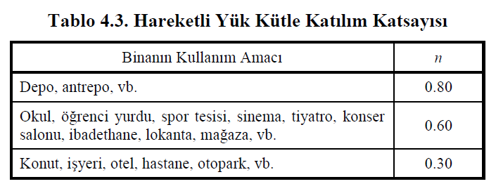
Table 4.3 Live Load Mass Participation Coefficient is under user control in the calculations made with Equation 4.16 .
ICONS
g = Gravitational acceleration [m / s 2 ]
m j (S) = Singular mass acting on typical finite element node j [t]
n = Live load participation coefficient
w j (S) = Typical finite element node j singular weight acting [kN]
w G, j (S) = single constant weight acting on typical finite element node j [kN]
w Q, j (S) = typical finite element node j acting singular additional (live load effect) weight [kN]
G = constant load effect
Q = Live load effect
Structural system elements are modeled as rod finite element (column, beam) or shell finite element (curtain, floor). Masses with respect to constant load G and live load Q are defined as the compounds of masses distributed over the nodes of finite elements. These singular masses defined at the nodes of finite elements are taken into account in a way that corresponds to two horizontal and vertical translational degrees of freedom.
Where the joint point (bar or shell) of a typical finite element is j, the constant load, G and live load, mass due to the effect of Q at j point are calculated by Equation (4.16) .

For j point of any finite element; w G, j (S) represents the constant load (G) at the node of the finite element and w Q, j (S ) represents the live load (Q) at the node of the finite element. In this case, the singular mass m j (S) value acting on the j node of the finite element is found by the relation w j (S) / g. Where g represents the acceleration of gravity.
Live load mass participation coefficient, n, is a coefficient specified in Table 4.3 of TBDY and determined according to the building use purpose.
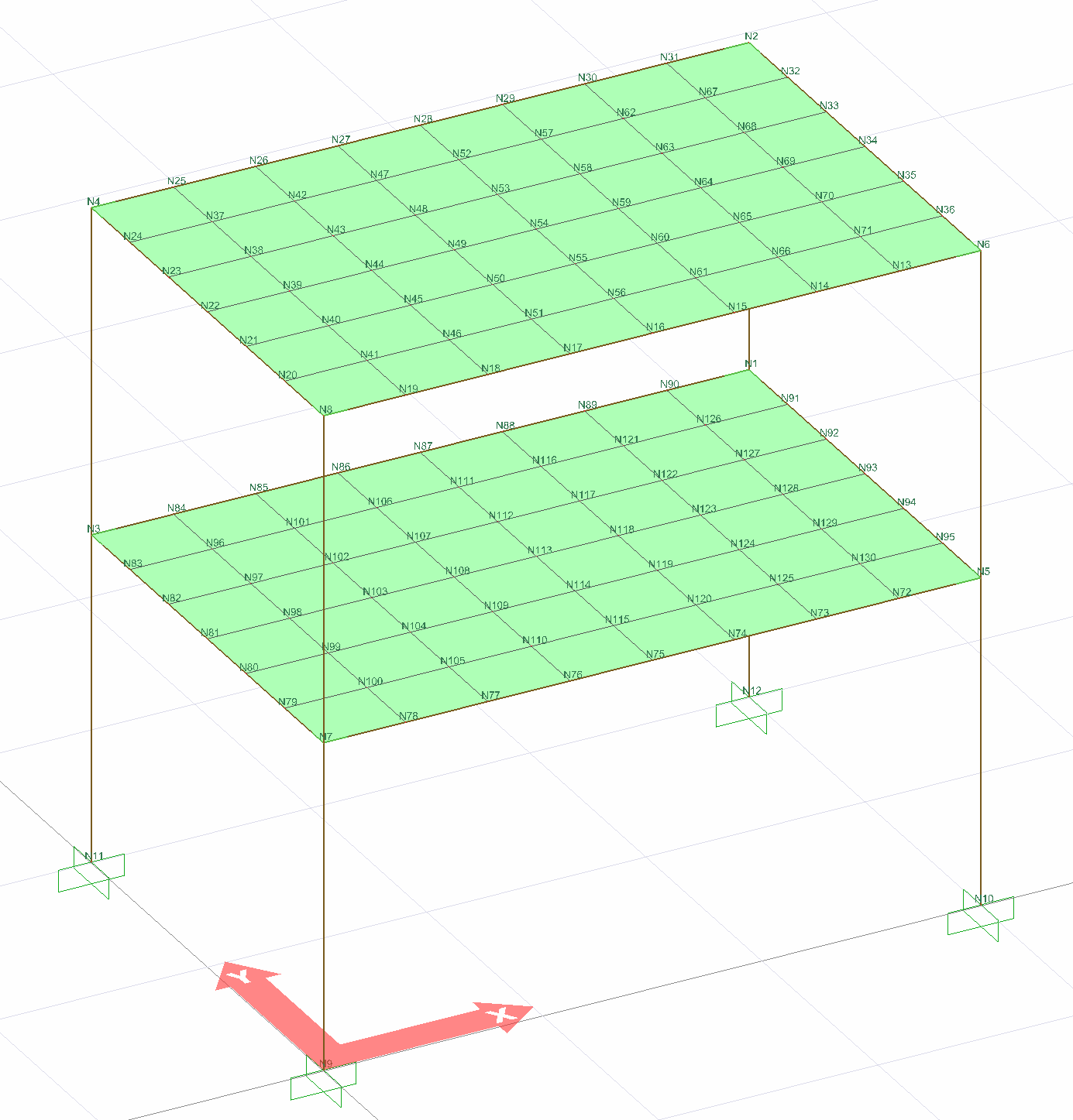
The masses formed at the nodes of the finite elements of the structure under the effect of fixed and live loads are calculated automatically in accordance with the above conditions. The following figure shows the finite element joints of a system consisting of bar and shell elements. Masses calculated according to the above criteria are defined at these nodes. In this case, the individual masses are automatically defined to take into account the effects of fixed and live load on the joints at the two ends of the frame elements and the joints at the four ends of the shell elements.
Next Topic
Related Topics