
ICONS
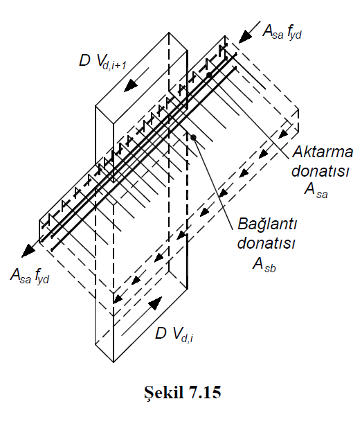
A sa = The area of the transfer reinforcement remaining from the required for bending strength
A sb = The area of the connection reinforcement remaining from the required for the bending strength
D = Strength Excess Coefficient
f yd = Design yield strength of the reinforcement
V d = Earthquake force to be transferred from the slab to the curtain in a strong direction
V d , i = Shear force generated in the upper section of the wall below the floor level
V d, i + 1 = Shear force generated in the lower section of the wall above the floor level
μ = Shear friction coefficient
TBDY Article 7.11.5 - The earthquake force to be transferred in a strong direction from the slab to the curtain or the curtain arm in buildings with non-beam floors or in buildings with beams, where earthquake loads must be shown to be safely transferred from the floors to vertical bearing elements, Resistance Excess of earthquake effects occurring in the lower and upper sections of the floor level DV d, which is calculated by taking the coefficient D into account, will be calculated as the difference of shear forces. This force difference is the sum of the axial tensile strengths formed by the beams or slab reinforcements, which are stuck to the curtain from both sides in a strong direction and remaining from the required bending strength, are 2A hrs f yd.and the sum of μA sb f yd of the shear friction strength created by the remaining flooring reinforcement from the necessary for the bending strength at the joints of the floor and the wall .
The amount of axial reinforcement (transfer reinforcement) stuck to the wall in a strong direction will not be reduced along the length of the wall, which is calculated, the shear friction (connection) reinforcement will provide the clamping conditions both inside the wall and in the slab.
Shear friction will be calculated in accordance with TS 500 in slab and curtain joints, and μ ≤1.0 value will be used for the friction coefficient. It should be taken into account that the amount of transfer reinforcement can be reduced by starting from the wall surface where the reinforcement is stuck, as it moves away from the wall face.
Between the transmission elements formed in this way and the flooring, the shear friction control will be made separately along the transmission element length (Figure 7.15) .
The earthquake force to be transferred from the floors to the curtain or curtain arm in a strong direction is taken as the difference of shear forces occurring in the lower and upper sections of the floor level. This shear force is transferred by the sum of the friction shear of the reinforcements at the slab wall intersection and the tensile strengths of the reinforcements stuck into the curtain in a strong direction. An example of a report is given below and details of the calculation steps are explained.