
Analysis settings that vary depending on the TBDY 2018 are explained in detail.
TBDY 2018 Options Tab
|
Specifications |
|---|
|
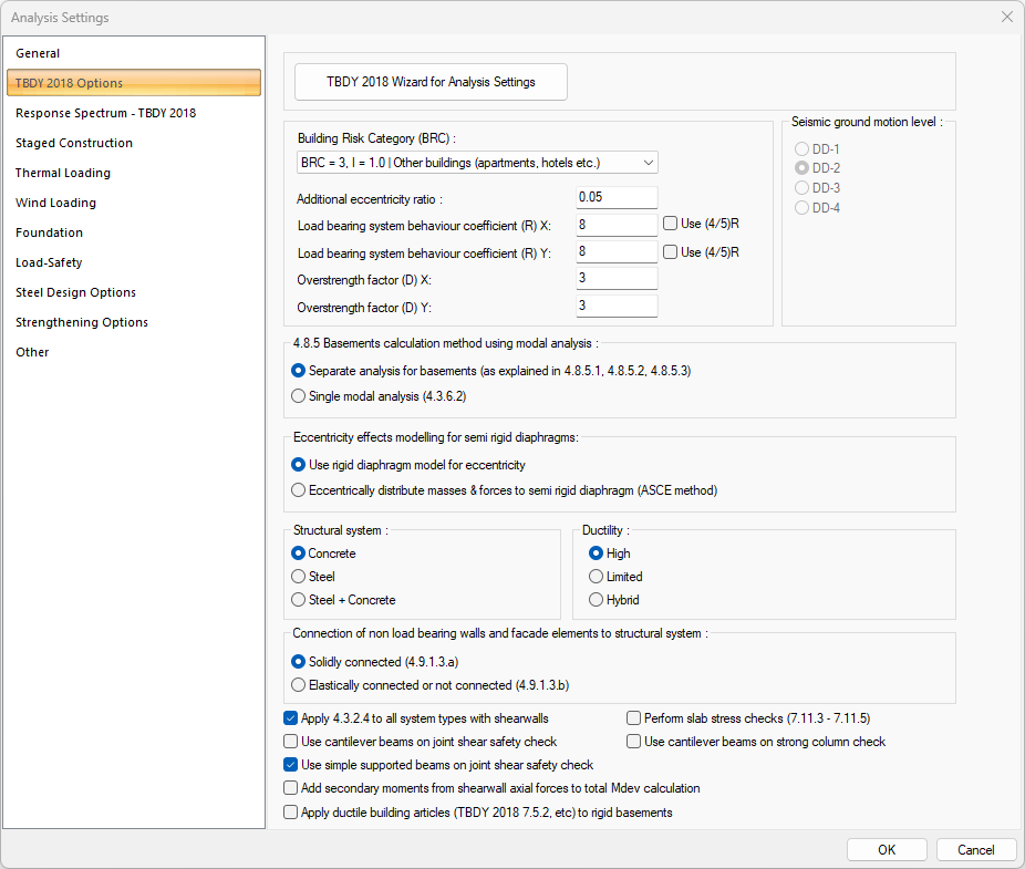
2018 TDY Wizard for Analysis Settings It displays the analysis settings wizard where the parameters specific to TDBY 2018 are determined step by step. On the wizard screen, you can assign the earthquake ground motion level, site class, design spectra, building risk category, seismic design category, stories, building height class, performance level, structural system, slab type, diaphragm, ductility and R coefficient values to be used. At the end of the process, values such as earthquake zone, ductility, strength excess coefficient etc. according to the parameters selected automatically change on this tab. |
|
Building risk category (BRC) Building risk category value is selected from the list according to the purpose of use of the building. It is one of the parameters selected in 2018 TDY wizard for analysis settings, and this row is automatically refreshed when the wizard is used |
|
Additional eccentricity ratio The eccentricity ratio to be used during the analysis is given as a percentage. |
|
Load bearing system behavior coefficient (R) X It is the load bearing system behavior coefficient value for the X direction. It is one of the parameters selected in 2018 TDY wizard for analysis settings, and this row is automatically refreshed when the wizard is used. |
|
Load bearing system behavior coefficient (R) Y It is the load bearing system behavior coefficient value for the Y direction. It is one of the parameters selected in 2018 TDY wizard for analysis settings, and this row is automatically refreshed when the wizard is used. |
|
Use (4/5) R In case the limit values of the curtain overturning moments are not met, the box in the relevant direction is checked, instead of the entered R coefficient, (4/5) R is used in the analysis. The analysis must be repeated after the relevant box is marked. |
|
Overstrength factor (D) X It is the strength excess coefficient value for the X direction. It is one of the parameters selected in 2018 TDY wizard for analysis settings, and this row is automatically refreshed when the wizard is used |
|
Overstrength factor (D) Y It is the coefficient of strength excess for the Y direction. It is one of the parameters selected in 2018 TDY wizard for analysis settings, and this row is automatically refreshed when the wizard is used |
|
4.8.5 Basements calculation method using modal analysis 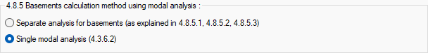
Choose one of the separate analysis for baements or single modal analysis calculation method. |
|
Use rigid diaphragm model eccentricity It is a mass model made with the assumption of a rigid diaphragm to calculate the eccentricity effect. |
|
Eccentrically distribute masses & forces to semi rigid diaphragm (ASCE) It is a mass model made by distributing the masses defined in the semi-rigid diaphragm assumption to create +5% -5% additional eccentricity to calculate the eccentricity effect. |
|
Structural system 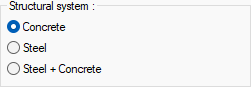
If the building block consists of only concrete elements, Concrete, if it consists of only steel elements, Steel + Concrete option is selected if it consists of concrete and steel elements. It is one of the parameters selected in 2018 TDY wizard for analysis settings, and this row is automatically refreshed when the wizard is used. |
|
Ductility 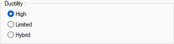
If the building will be built with high ductility level, high, if the building design will be made with limited ductility level, limited, if the ductility level will be mixed, hybrid option is selected. It is one of the parameters selected in 2018 TDY wizard for analysis settings, and this row is automatically refreshed when the wizard is used |
|
Connection of non load bearing walls and facade elements to 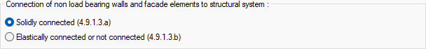
1st option is marked, if hollow or non-void infill walls and facade elements made of brittle material are completely adjacent to the frame members without any flexible joints or connections between them, If flexible joints are made between infill walls made of brittle material and frame elements, the facade elements are connected to the outer frames with flexible connections, or the infill wall element is independent from the frame, option 2 is marked. Relative story displacements are made according to the limit determined according to the given option. |
|
Seismic ground motion level 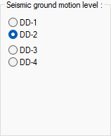
The option is marked according to the location of the building. It is one of the parameters selected in 2018 TDY wizard for analysis settings, and this row is automatically refreshed when the wizard is used. |
|
Apply 4.3.2.4 to all system types with shearwalls In case of failure to provide controls regarding the shear moments in buildings with DTS1, 1a, 2, 2a, R coefficient value (4/5) R takes the calculations. |
|
Use cantilever beams on joint shear safety check This option is simple in the column-beam shear safety check and specifies whether cantilever beams should be taken with care. If marked, the column support of the beams whose one side is empty, the other side is sitting on the column is included in column-beam shear safety, if not marked, these elements are not put into control. |
|
Use simple supported beams on joint shear safety check This option specifies whether or not simple supported beams will be taken into consideration during column-beam shear safety check. |
|
Add secondary moments from shearwall axial forces to total Mdev calculation If the option is selected, the shear forces of the beams that do not meet the tie beam adherence requirement are taken into consideration in the shearwall overturning moment control. |
|
Apply ductile building articles to rigid basements It is the option that determines whether the ductility level conditions given within the scope of the regulation will be applied to the floors specified as rigid basement floors. If the option is selected, the substances in question are applied to the elements in the rigid basement floor. In cases where you do not want the materials to be applied in rigid basements, you can cancel the option. |
|
Perform slab stress checks (7.11.3-7.11.5) By selecting the option, slab stress checks are performed. |
|
Use cantilever beams on strong column check This option specifies whether the cantilever beams connected to the column will be taken into account in strong column checks. |
Response Spectrum - TBDY 2018 Tab
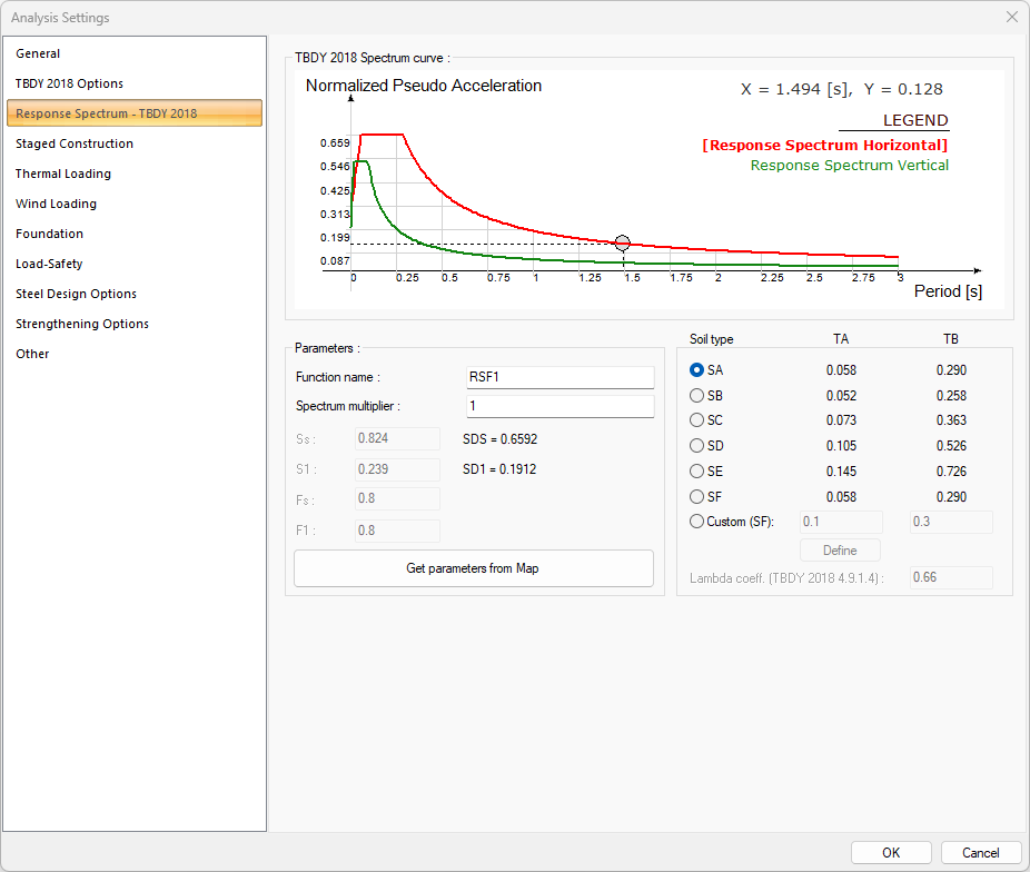
The parameters used in the spectrum function can be determined with the 2018 TDY wizard for analysis settings, the parameters in this line are automatically refreshed when the wizard is used. Also, the parameters in the dialog can be changed.
The spectrum curve is determined according to the selected soil class. You can enter the short-period map spectral acceleration coefficient Ss required for the spectrum curve and the map spectral acceleration coefficient S1 for a 1-second period yourself or you can read it online from the AFAD map.
|
Specifications |
|---|
|
Get parameters from map When the button is pressed to read parameters from the AFAD Map, the program runs a 3-step wizard. In the wizard, the interface to select a point from the map for earthquake ground motion level, ground class and design spectrum is displayed. The parameters are read automatically when the wizard is terminated. 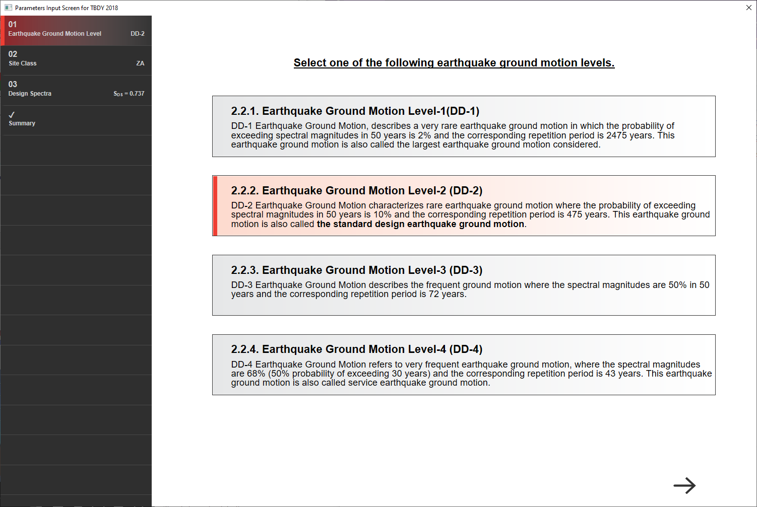
|
|
Spectrum curve 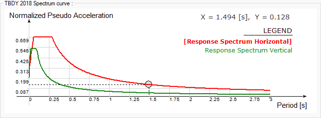
The spectrum curve resulting from the settings is shown. |
|
Function name The name of the spectrum function. |
|
Spectrum multiplier Factor of spectrum function. |
|
Ss 0.2 sec spectral acceleration of spectrum function. |
|
SDS Design earthquake spectral response acceleration parameter at short period. |
|
S1 1 sec spectral acceleration of spectrum function. |
|
SD1 Design earthquake spectral response acceleration parameter at 1-s period. |
|
Fs Short-Period Site Coefficient. |
|
Fs Long-Period Site Coefficient. |
|
Soil type Soil type that determine the spectrum curve are determined according to the ground on which the building is located. The spectrum curve is renewed according to the selected soil type. It is one of the parameters selected in 2018 TDY wizard for analysis settings, and this row is automatically refreshed when the wizard is used. 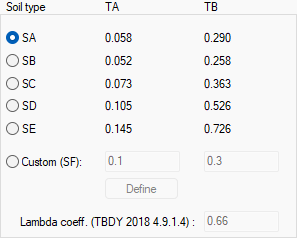
|
|
Custom It is used to define any curve other than the spectrum curve determined according to the soil type in the earthquake code. 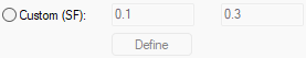
You can mark this line and click the Define button to make the definition you want. |
|
Lambda coeff. The Lambda coefficient, which is calculated automatically depending on the earthquake parameters DD2 and DD3 and used in limiting the relative floor displacements, is shown in this line for information purposes. |
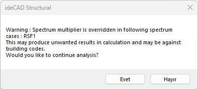
A warning is displayed when the spectrum multiplier is entered as less than 1.
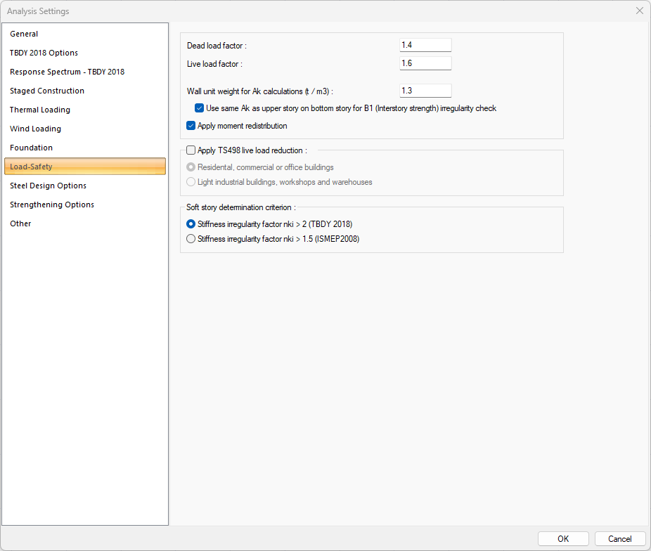
Load-Safety Tab
|
Specifications |
|---|
|
Dead load factor The value determining how much the dead loads will be increased is entered. |
|
Live load factor The value determining how much the live loads will be increased is entered. |
|
Wall unit weight for Ak calculations The required wall unit weight is entered for the calculation of the Ak value used in determining the strength irregularity between neighboring stories. |
|
Use same Ak as upper story on bottom story for B1 (Interstory strength) irregularity check If the option is selected, the Ak value of the bottom story will be taken the same as the upper story. If you do not want the Ak value to be taken as the same as the upper story, you can define the Ak value yourself in the "Story parameters" dialog under the "Analysis" menu. |
|
Apply moment redistribution If checked, the redistribution agent is applied to the system after the system has been decoded in the program. It is not applied if it is not checked. |
|
Apply TS498 live load reduction 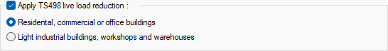
If checked, Live Load Reduction conditions are applied in the program. According to the relevant article; In the calculation of structural elements bearing loads of at least more than three times, it is possible to reduce the result within certain bases by adding each story live load. The amount of reduction or, depending on it, the reduction values are tabulated separately for different, light industrial buildings, workshops, warehouses and residental, commercial or office buildings. The relevant option is marked according to the intended use of the building. % decrement value: a) From 20% to 80% in residental, commercial or office buildings. b) It is applied from 10% to 40% in light industrial buildings, workshops and warehouses. |
|
Soft story determination criterion 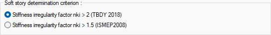
The limit value used in soft story control changes according to the selected option. |
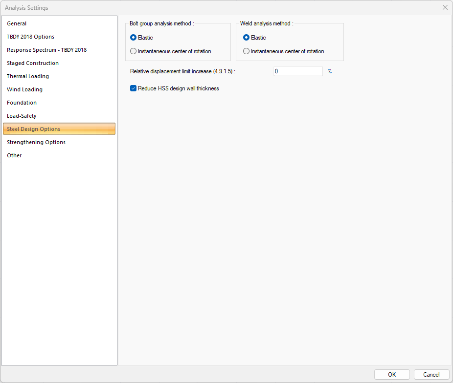
Steel Design Options Tab
|
Specifications |
|---|
|
Bolt group analysis method 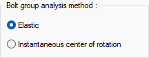
Two main calculation methods, the elastic method or the instantaneous center of rotation methods, can be used in connections subject to eccentric force. Click the option you want to apply. |
|
Weld analysis method 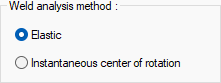
Two main calculation methods, the elastic method or the instantaneous center of rotation methods, can be used in connections subject to eccentric force. Make your choice by clicking on the differences in design philosophy of both methods and the efficiency rates in the combination types used. |
|
Relative displacement limit increase (4.9.1.5) According to TBDY 4.9.1.5, it is the increase rate of the relative story displacement limit value that can be used for single-storey buildings where all seismic loads are carried by moment-transmitting steel frames. This value can be made at most 50% according to 4.9.1.5. |
|
Reduce HSS design wall thickness It can be selected by the user to take into account the section losses at the production stage of the HSS design wall thickness as prescribed by AISC. |
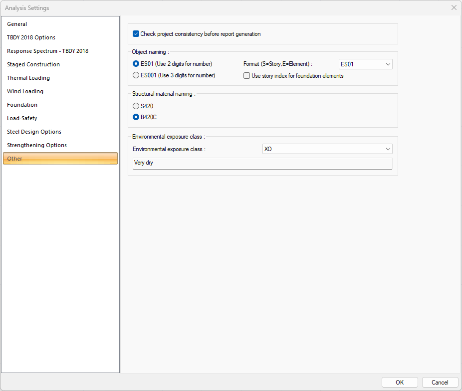
Other Tab
|
Specifications |
|---|
|
Check project consistency before report generation If it is desired to list the conformity conditions in terms of regulations while receiving the report, it is marked. If the option is not selected, the program will not notify the project designer at the beginning of the report. |
|
Object naming 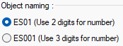
How element naming will be selected. The option selected in this section and the story index entered in the story parameters are used together. For example, let the story index entered in story parameters be 1. Let ES01 option be ticked as naming. S1 name will be considered as S101. If no index was entered in the story general parameters, it would be S01. If the ES001 option is selected in the naming, the name S1 will be considered as S1001. If the index was not entered in the general parameters of the story, this naming would be S001. |
|
Format In object naming, the format and story-element ordering is selected from the drop-down list. |
|
Use story index for foundation elements Story indices entered in story parameters are also used in the foundation. |
|
Structural material naming 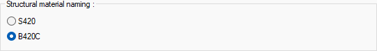
How the naming of the reinforcement material to be seen in the reports is selected. |
|
Environmental exposure class 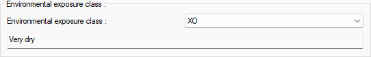
Environmental exposure class is selected from the list according to TS EN 206, schedule 1. Information arranged according to the selected class is indicated on the letterheads given in the drawing details. |
Next Topic
Related Topics