How does ideCAD define the redundancy factor, ρ, according to ASCE 7-16?
-
The redundancy factor, ρ, is automatically obtained horizontal seismic forces according to ASCE 7-16 Section 12.3.4.
SYMBOLS
Eh = Horizontal seismic load effect
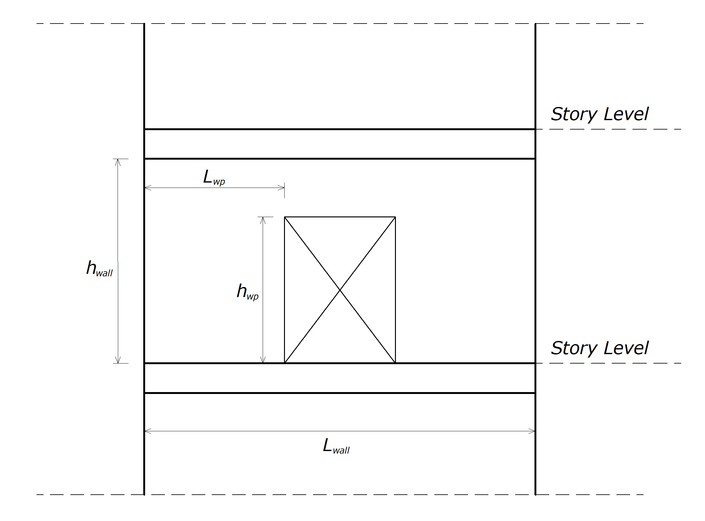
hwall = height of shear wall
hwp = height of wall pier
Lwall = length of shear wall
Lwp = length of wall pier
ρ = Redundancy factor
QE = Effects of horizontal seismic forces from V or Fp
Download ideCAD for ASCE 7-16
Redundancy is an important property for structures designed with the expectation that damage will occur. Redundant structures have alternative load paths so that if some elements are severely damaged and lose load-carrying capacity, other elements will be able to continue to provide a safe load path. Adequate redundancy is ensured when a large number of plastic hinges must form throughout the structure progressively before the formation of a mechanism and when no element is required to provide the full seismic resistance of the structure. The redundancy factor, ρ, is automatically obtained horizontal seismic forces according to ASCE 7-16 Section 12.3.4.
The Redundancy factor, ρ, is used for the seismic force-resisting system in each of two orthogonal directions for all structures in accordance with Eq. 12.4-3.
'%3e%3cg transform='translate(167%2c0)'%3e%3cg transform='translate(-13%2c0)'%3e%3cg transform='translate(0%2c-25)'%3e%3cuse xlink:href='%23MJMATHI-45' x='0' y='0'%3e%3c/use%3e%3cuse transform='scale(0.707)' xlink:href='%23MJMATHI-68' x='1044' y='-213'%3e%3c/use%3e%3cuse xlink:href='%23MJMAIN-3D' x='1523' y='0'%3e%3c/use%3e%3cuse xlink:href='%23MJMATHI-3C1' x='2580' y='0'%3e%3c/use%3e%3cg transform='translate(3097%2c0)'%3e%3cuse xlink:href='%23MJMATHI-51' x='0' y='0'%3e%3c/use%3e%3cuse transform='scale(0.707)' xlink:href='%23MJMATHI-45' x='1119' y='-213'%3e%3c/use%3e%3c/g%3e%3cuse xlink:href='%23MJMAIN-28' x='9529' y='0'%3e%3c/use%3e%3cg transform='translate(9919%2c0)'%3e%3cuse xlink:href='%23MJMAIN-31'%3e%3c/use%3e%3cuse xlink:href='%23MJMAIN-32' x='500' y='0'%3e%3c/use%3e%3cuse xlink:href='%23MJMAIN-2E' x='1001' y='0'%3e%3c/use%3e%3cuse xlink:href='%23MJMAIN-34' x='1279' y='0'%3e%3c/use%3e%3c/g%3e%3cuse xlink:href='%23MJMAIN-2212' x='11921' y='0'%3e%3c/use%3e%3cuse xlink:href='%23MJMAIN-33' x='12922' y='0'%3e%3c/use%3e%3cuse xlink:href='%23MJMAIN-29' x='13422' y='0'%3e%3c/use%3e%3c/g%3e%3c/g%3e%3c/g%3e%3c/g%3e%3c/svg%3e)
The Redundancy factor, ρ, is 1.0 for the following:
-
Structures assigned to Seismic Design Category B or C
-
P-delta effects and story drift calculation
-
Design of collector elements, splices, and their connections using the seismic load effects with the overstrength factor of Section 12.4.3
-
Design of members or connections where the seismic load effects, including overstrength factor
-
Diaphragm loads determined using Eq. (12.10-1), including the limits imposed by Eqs. (12.10-2) and (12.10-3)
-
Structures with damping systems designed per ASCE Chapter 18
-
Design of structural walls for out-of-plane forces, including their anchorage
Redundancy Factor, ρ, for Seismic Design Categories D through F
For structures assigned to Seismic Design Category D with extreme torsional irregularity as defined in Table 12.3-1, Type 1b, ρ equals 1.3.
For other structures assigned to Seismic Design Category D and for structures assigned to Seismic Design Categories E or F, ρ is controlled automatically. Moreover, the software uses 1.3 unless one of the following conditions occurs.
Seismic Design Categories E and F are not allowed to use because extreme torsional irregularities are prohibited.
-
Each story resisting more than 35% of the base shear in the direction of interest according to Table 12.3-3.
-
Structures are regular in plan at all levels provided that the seismic force-resisting systems consist of at least two bays of seismic force-resisting perimeter framing on each side of the structure in each orthogonal direction at each story resisting more than 35% of the base shear.
|
Lateral Force-Resisting Element |
Requirement |
|---|---|
|
Braced frames |
Removal of an individual brace, or connection thereto, would not result in more than a 33% reduction in story strength, nor does the resulting system have an extreme torsional irregularity (horizontal structural irregularity Type 1b). |
|
Moment frames |
Loss of moment resistance at the beam-to-column connections at both ends of a single beam would not result in more than a 33% reduction in story strength; nor does the resulting system have an extreme torsional irregularity (horizontal structural irregularity Type 1b). |
|
Shear walls or wall piers with a height-to-length ratio greater than 1.0 |
Removal of a shear wall or wall pier with a height-to-length ratio greater than 1.0 within any story, or collector connections thereto, would not result in more than a 33% reduction in story strength; nor does the resulting system have an extreme torsional irregularity (horizontal structural irregularity Type 1b). The shear wall and wall pier height-to-length ratios are determined as shown in Figure. |
|
Cantilever columns |
Loss of moment resistance at the base connections of any single cantilever column would not result in more than a 33% reduction in story strength; nor does the resulting system have an extreme torsional irregularity (horizontal structural irregularity Type 1b). |
|
Other |
No requirements. |