
The total curvature demand is obtained using the displaced axis rotation calculated while performing the linear performance analysis, the yield moment and yield curvature values calculated using the moment curvature relation.
-
The total curvature demand ϕ t of the element end section is automatically calculated.
ICONS
E = Concrete modulus of elasticity
h = Section height
I = Moment of inertia
L p = Plastic hinge length
l c = Element net opening
M y = Effective yield moment
M yi = Effective yield momentat i end
M yj = Effective yield moment at j end
Δ = Element translation between nodes
ϕ y = Flow curvature
ϕ t = Total curvature
θ p =Plastic rotation demand
θ y = Flow rotation
θ yi = flow rotation at end i
θ yj = flow rotation at end j
θ k = Displaced axis rotation
θ ki = displaced axis rotation at end i
Evaluation of existing buildings and design according to Strain (ŞGDT) determining the seismic performance of the linear approximation calculation method used total curvature lead the end section element φ t , Eq. (2.15) is calculated by.
In this equation, θ k , the stopped rotation axis displacement means and Eq. (15A.1) is calculated by.
θ y refers to its return to flow. The linear calculation method used in determining the seismic performance of this rotational flow Section 15A.3 TBDY indicated at Frame Elements in Pour Rotation and TBDY Section 15A.4 as indicated in Flow Rotation of the curtain elements are calculated by equations.
The relationship between the yield rotation and end moments at the i and j ends of a bending frame element that passes to a flowing state at both ends as specified in TBDY Section 15A.3 is given in Equation (15A.3) . EI is the bending stiffness of the unbroken section. M yi and M yj are the effective yield moments at the i and j ends, respectively. M yi and M yj are calculated by the moment-curvature relationship calculated according to the section material model and the reinforcement placement.
The relationship between the yield rotation and yield moment of a bending element defined as a curtain wall in TBDY Section 15A.4 is given in Equation (15A.4) . EI is the bending stiffness of the unbroken section. M y is the effective torque . It is calculated by the moment-curvature relation calculated according to the material model of the wall section and the reinforcement placement.
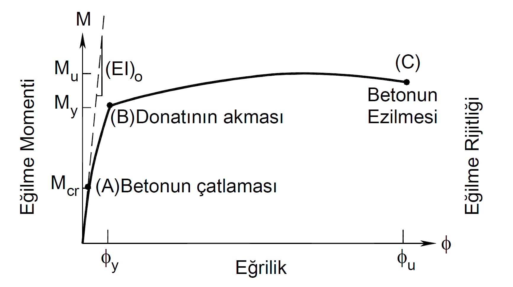
The term expressed with ϕ y in Eq. (15.2) is the flow curvature at the element end section. ϕ y value is found by the moment-curvature relationship calculated according to the section material model and the reinforcement placement. In the moment-curvature graph below, the point (B) is the moment M y when the reinforcement flows and the curvature ϕ y when the reinforcement flows . This moment-curvature relation drawn is created with the material models created by considering the knowledge level coefficient and the available material strengths .
In Eq. (15.2) , L p is the length of the plastic hinge and it is calculated as half the section height in the effective direction.
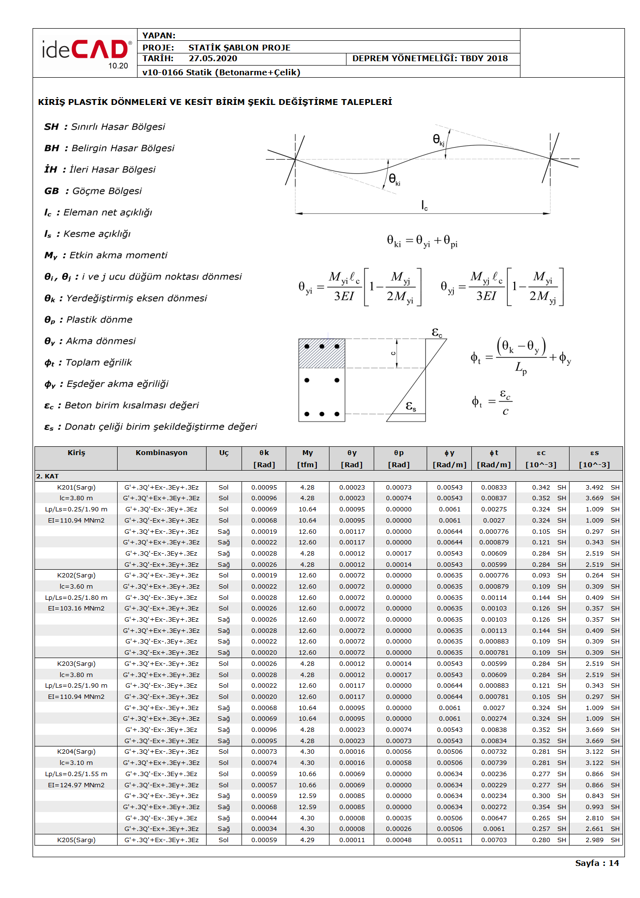
The following reports the total demand for beam curvature, for example, φ t , return flow θ y , the yield torque M y , plastic rotation demand θ p , yield curvature φ y , φ total curvature lead t is shown.
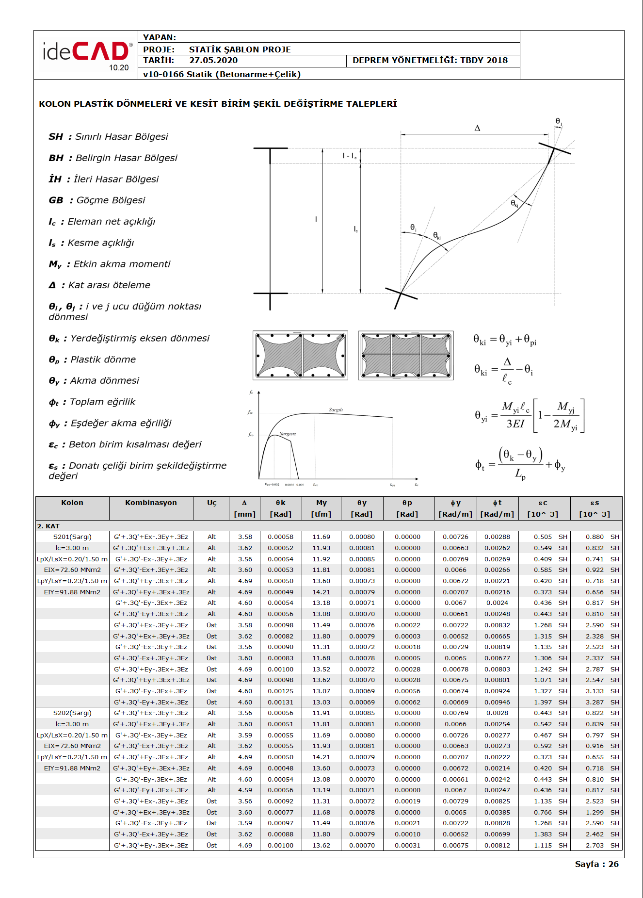
The following example reports the total curvature lead to columns φ t , return flow θ y , the yield torque M y , plastic rotation demand θ p , yield curvature φ y , φ total curvature lead t is shown.
Next Topic
Related Topics