
How does ideCAD calculate steel members' flexural strength according to AISC 360-16?
-
The flexural strength of steel elements is calculated automatically according to AISC 360-16.
-
The nominal flexural strength limit states of yielding and lateral-torsional buckling are controlled automatically according to AISC 360-16.
-
For design members for flexure, sections are automatically classified as compact, non-compact, or slender-element sections, according to AISC 360-16.
Symbols
Fy = Specified minimum yield stress
E = Modulus of elasticity of steel = 29,000 ksi (200 000 MPa)
Mn = The nominal flexural strength
λr = Limiting width-to-thickness parameter for noncompact element
λp = Limiting width-to-thickness parameter for compact element
-
The design flexural strength =
-
The allowable flexural strength =
Bending Member Definition
Bending (flexural) members are structural members that support transverse loads and are, therefore, subjected primarily to flexure or bending.
Members that are affected by bending moment around any of their principal axes. In the members with the effect of bending, the loads should act in the plane parallel to the principal axis passing through the shear center, or the member should be supported against torsion at the load impact points and supports.
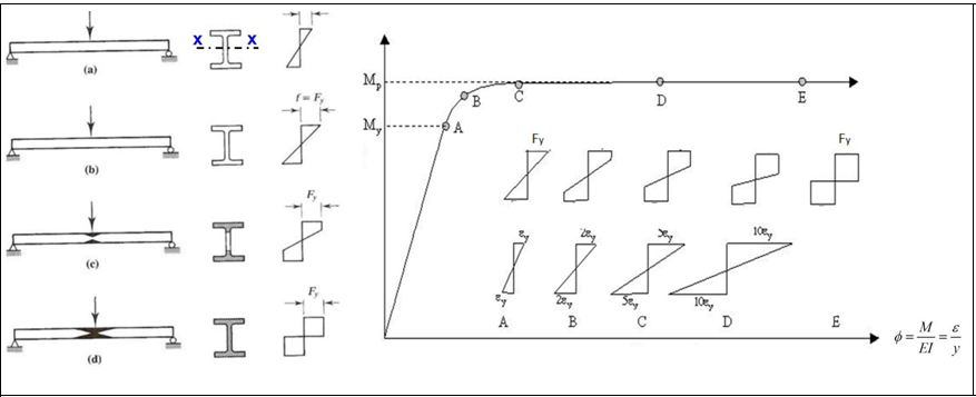
Yielding Limit State
It is a situation where the beam's cross-section is dimensioned to remain stable until it becomes plastic above the effect of bending if the local buckling of the compression flange and the lateral torsional buckling are prevented. In this case, the characteristic moment strength can be considered equal to the plastic moment strength.
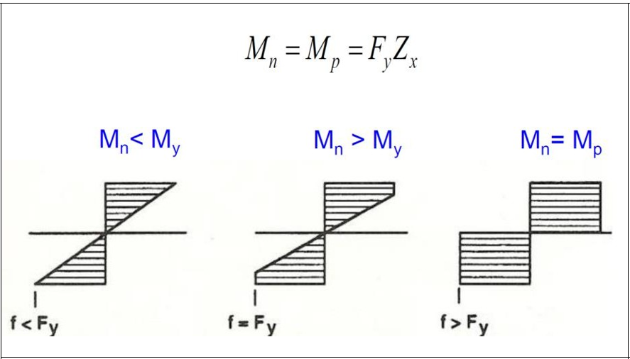
The yield moment is that the upper fiber of the section above the influence of the bending moment reaches the yield stress.
The plastic moment is the moment value when all fibers of the section above the effect of bending moment reach the yield stress.
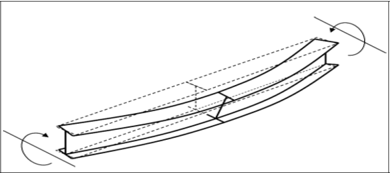
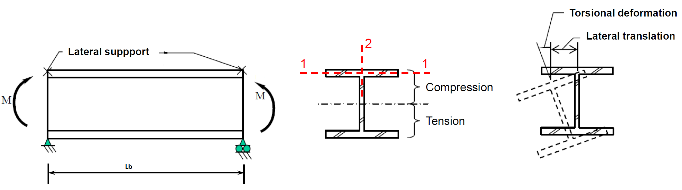
Lateral Torsional Buckling Limit State
The part of the beam in the compression flange area acts like an axially loaded compression frame. The beam section cannot reach its full bending capacity if the compression flange's stability is insufficient. Similar to the compression elements, global buckling or loss of stability in cross-sectional parts that may occur with local buckling determines the collapse limit state. This type of buckling of the compression flange is called lateral torsional buckling.
The rectangular flange as a column would ordinarily buckle in its weak direction by bending about an axis such as the 1-1 axis, but the web provides continuous support to prevent such buckling. At higher compressive loads, the rectangular flange will tend to buckle by bending about axis 2-2. This sudden buckling of the flange about its strong axis in a lateral direction is commonly referred to as lateral buckling.
Local Buckling
Local buckling occurs when some part or parts of the cross-section of a bending member are so slender that they buckle locally in compression. However, the flexural strength corresponding to any buckling mode cannot be developed if the cross-section element is so thin that local buckling occurs.
The measure of this susceptibility is the width-thickness ratio of each cross-sectional element.
Limit values for the classification of cross-sections for the local buckling boundary condition are given in AISC 360-16 B.4 and Table B4.1b for cross-sections under compressive force.
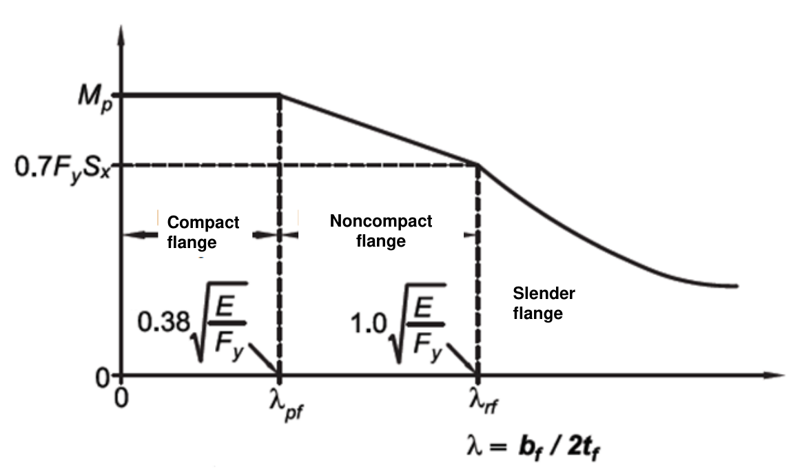
For design members for flexure, sections are classified as compact, noncompact, or slender-element sections.
Width-to-thickness ratio, λ
If λ ≤ λp, the element is compact,
If λp < λ ≤ λr, the element is noncompact,
If λ > λr, the element is slender.
|
TABLE B4.1b
|
|||||
|---|---|---|---|---|---|
|
Case |
Element Description |
Width-to Thickness Ratio |
Limiting Width-to-Thickness Ratio |
Examples |
|
|
λp
|
λr
|
||||
|
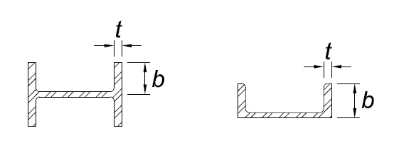
10 |
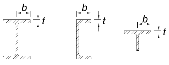
Flanges of rolled I-shaped sections, channels, and tees |
b/t |
|
|
|
|
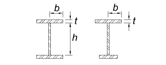
11 |
Flanges of doubly and singly symmetric I-shaped built-up sections |
b/t |
|
|
|
|
12 |
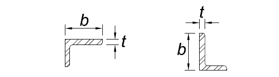
Legs of single angles |
b/t |
|
|
|
|
13 |
Flanges of all I-shaped sections and channels in flexure about the minor axis |
b/t |
|
|
|
|
14 |
Stems of tees |
d/t |
|
|

|
|
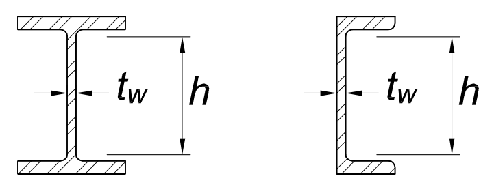
15 |
Webs of doubly symmetric I- shaped sections and channels |
h/tw |
|
|
|
|
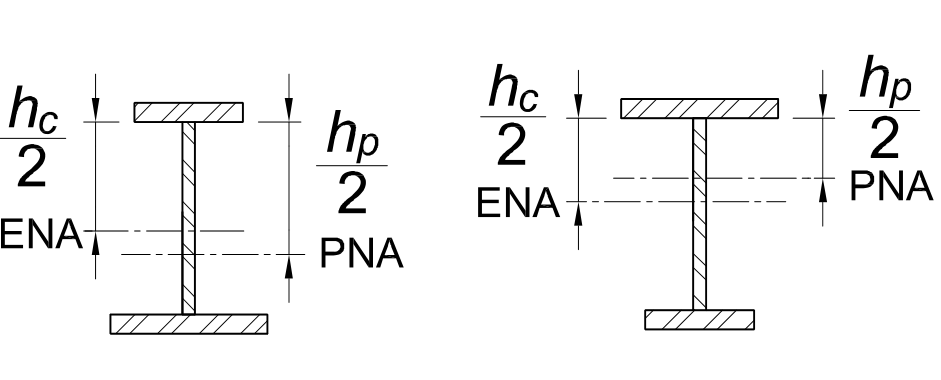
16 |
Webs of singly symmetric I-shaped sections |
hc/tw |
|
|
|
|
17 |
Flanges of rectangular HSS |
b/t |
|
|
|
|
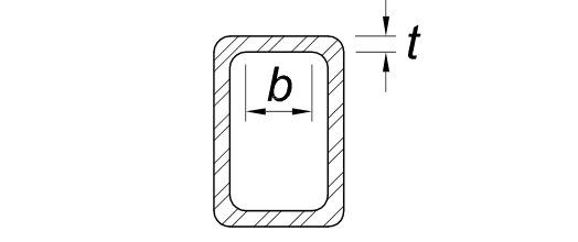
19 |
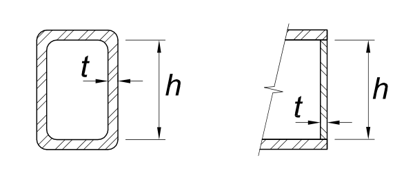
Webs of rectangular HSS and box sections |
h/t |
|
|
|
|
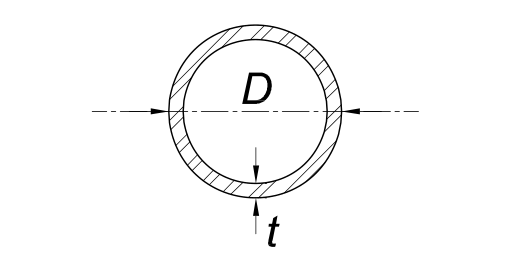
20 |
Round HSS |
D/t |
|
|
|
|
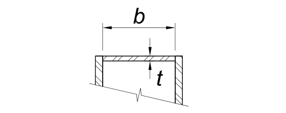
21 |
Flanges of box sections |
b/t |
|
|
|