
ICONS
A sh = Transverse reinforcement area (rectangular section) [mm 2 ]
A os = Area of transverse reinforcement (circular section) [mm 2 ]
a i = Distance between the axes of longitudinal reinforcement supported by a stirrup arm horizontally [mm]
b o = core concrete Section size between the axes of the winding stirrups [mm]
b k = Core size (distance between the outermost transverse reinforcement axes) [mm]
D = Distance between spiral / coil reinforcement axes [mm], [Equation (5.4e)]
db = Diameter of longitudinal reinforcement (average attensile) [m]
f ce = Average (expected) compressive strength of concrete [MPa]
f ck = Characteristic compressive strength of concrete [MPa]
f ywe = Average (expected) yield strength of transverse reinforcement [MPa]
h o = Cross section size between the axes of stirrups surrounding the core concrete [mm]
L p = Plastic hinge length [m]
L s = Shear clearance [m]
s = Confinement reinforcement spacing [m]
αse = Coefficient of efficiency of confinement reinforcement
ϕ y = Yield curvature [m -1 ]
ϕ u = Shear curvature [m -1 ]
ω we = Mechanical reinforcement ratio of effective confinement reinforcement
ρ sh = Volumetric ratio of transverse reinforcement in the direction considered
ε c (GÖ) = Allowable confined concrete unit shortening limit for Pre-migration performance level
ε c (KH) = Allowable confined concrete unit shortening limit for Controlled Damage performance level
ε c(SH) = Permissible confined concrete unit shortening limit for Limited Damage performance level
ε s (DAM) = Allowable reinforcement steel unit deformation limit for Preventing Migration performance level
ε s (KH) = Allowable reinforcement steel unit for Controlled Damage performance level deformation limit
ε s (SH) = Allowable reinforcement steel strain limit for Limited Damage performance level
θ p (KH) = Controlled DamageAllowable plastic rotation limit for performance level [rad]
θ p (GÖ) = Allowable plastic rotation limit for Preventing Performance level [rad]
θ p (SH) = Allowable plastic rotation limit for Limited Damage performance level [rad]
TBDY Section 5.8. EVALUATION OF SHAPE CHANGES AND INTERNAL FORCES
5.8.1. Permissible Modification and Internal Force Limits for New Reinforced Concrete Building Elements
5.8.1.1 - Total concrete and reinforcement steel calculated according to the diffused plastic behavior model given in this Chapter for new reinforced concrete building elements, including Tall Buildings given in Chapter 13 , to be used in the performance assessment to be made for the Prevention of Migration ( LO ) Performance Level The permissible limits for unit deformations ε c (GÖ) and ε s (GÖ) are defined in (a) and (b) below :
(a) Concrete unit shortening for Pre-migration performance level: In
rectangular columns, beams and bulkheads:

In circular sections:

The first term in these relations refers to the unit shortening of uncoiled concrete (shell concrete). ω w to the mechanical reinforcement ratio of active hoops ' n shows:

In Eq. (5.4c) , α se is the coefficient of confinement reinforcement efficiency , ρ sh, min is the smaller of the volumetric transverse reinforcement ratio in two horizontal directions in the rectangular section, and f ywe shows the average (expected) yield strength of the transverse reinforcement:

In Eq. (5.4d) , A sh and ρ sh are the area and volumetric ratio of the transverse reinforcement in the direction considered, b k the core size in the perpendicular direction (the distance between the outermost transverse reinforcement axes), s the transverse reinforcement interval, b o and h o winding. It shows the dimensions of confined concrete measured from the axes of the reinforcement, a i shows the distance between the axes of the longitudinal reinforcement supported by a stirrup arm or crossty. The efficiency coefficient of the circular confinement reinforcement is given in Equation (5.4e) :

Here A os is the area of the spiral / confinement reinforcement, s is the transverse reinforcement spacing or pitch of the spiral, and D is the distance between the spiral / confinement reinforcement axes. N = 2 for circular stirrups and n = 1 for spiral reinforcement.
(b) Unit deformation for reinforcement steel for the Preventing Migration performance level:

Here ε indicates the unit elongation corresponding to the water tensile strength (See. TBDY ANNEX 5.A ).
5.8.1.2 - Prevention of immigrants (PISG) Performance Level to be used in the performance will be held for evaluation, Chapter 13 'in the high buildings , including its new reinforced concrete building element of this Chapter from the stacked plastic behavior calculated based on the model of the plastic rotations allowed for The boundary will be calculated with Equation (5.6) as a result of the curvature analysis to be made by considering the axial force acting on the cross section and the concrete and reinforcement steel models given in Annex 5A .
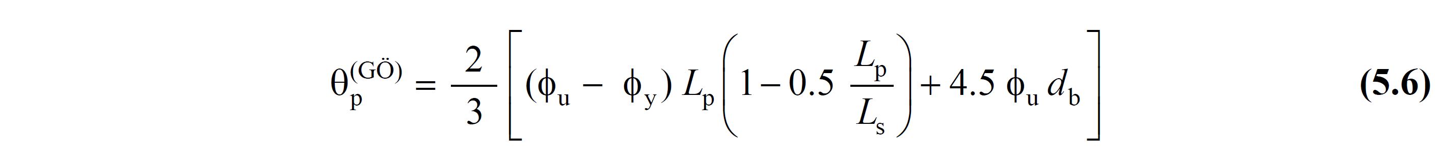
Wherein φ u , 5.8.1.1 from the concrete and reinforcement steel unit deformation they with Appendix 5 'in the concrete and reinforcement steel utilizing the model and the section to effect axial force derived from the analysis made based on the total curvature of the pre-collapse ' s is shown. The last term in Eq. (5.6) corresponds to the post-yield (up to pre-collapse) condition for the shear rotation of the reinforcement due to the elongation penetration .
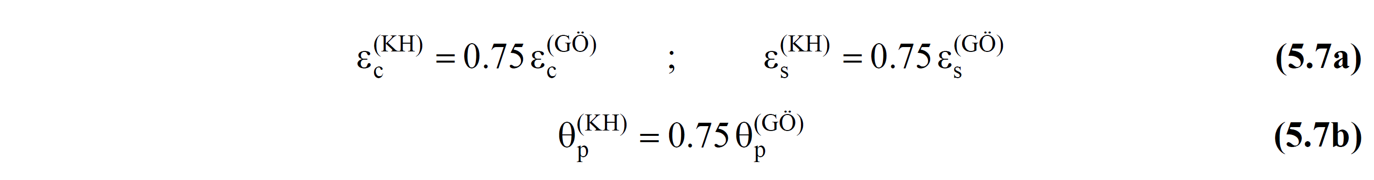
5.8.1.3 - Total permitted unit deformations for concrete and reinforcement steel calculated with the calculation methods given in this Section for new reinforced concrete building elements to be used in the performance evaluation to be made for the Controlled Damage (KH) Performance Level ε c (KH) and ε s ( The limits of plastic rotation θ p (KH) with KH) are defined in Equation (5.7) depending on the values defined in 5.8.1.1 and 5.8.1.2 for the Prevention of Migration performance level :
5.8.1.4 - Total permitted unit deformations of concrete and reinforcement steel calculated with the calculation methods given in this Section in new reinforced concrete building elements to be used in the performance evaluation to be made for Limited Damage (SH) Performance Level ε c (SH) and ε s (SH ) Is defined in Eq. (5.8a) :

For the calculation made by using the effective section stiffnesses defined in 5.4.5.2 , the formation of plastic joints in the carrier system for the SH performance level will not be allowed:

5.8.1.5 - With the calculation methods given in this Chapter for new reinforced concrete building elements, it will be shown that the internal force demands calculated for the Prevention of Migration performance case are smaller than the internal force capacities defined in Chapter 7 for the relevant elements . However, in calculating the internal force capacities, instead of characteristic material strengths, average (expected) material strengths given in Table 5.1 shall be taken as basis. Relevant rules for reinforced concrete tall buildings are given in Chapter 13 .
5.8.1.6 - Limits of permitted strain and internal force in the assessment of existing building elements are defined in Chapter 15 .