
ICONS
A c = Cross-sectional area of the column
f ck = Characteristic compressive strength of concrete
f cd = Design compressive strength of concrete
f yd = Design yield strength of longitudinal reinforcement
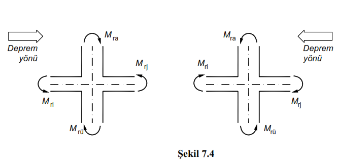
M ra = Bearing strength calculated according to f cd and f yd at the lower end of the free height of the column or wall torque
M r = column or in the upper end of the free height of the curtain for CDs and f yd 'calculated according to the ultimate moment
M r = Moment of positive or negative bearing capacity calculated according to f cd and f yd on the column or wall face at the left end of the beam
M rj = Negative calculated according to f cd and f yd on the column or wall face at the right end of the beam j positive bearing strength moment
N d = Axial force calculated under the combined effect of vertical loads and earthquake loads multiplied by the load factors.
V ik = Sum of shear forces calculated in the direction of the earthquake in all columns on the i'th floor of the building
V is =The sum of shear forces calculated in the direction of the earthquake considered in the columns where (M ra + M rü ) ≥ 1.2 (M ri + M rj ) is provided at both the lower and upper joints of the building. At the ends of the columns meeting the condition N d ≤ 0.10 A c f ck , Eq. Even if (7.3) is not provided, these columns are also not taken into account in the calculation of V is .
7.3.5. The Condition That Columns Are Stronger Than Beams
7.3.5.1 - In load-bearing systems consisting only of frames or a combination of walls and frames, the sum of the load-bearing moments of the columns joining each column-beam node will be at least 20% greater than the sum of the moments of bearing strength in the sections of the column face of the beams connecting to that node ( Figure. 7.4 ):

7.3.5.2 - Equation (7.3) will be applied separately for each earthquake direction and for both sides of the earthquake so as to give unfavorable results ( Figure 7.4 ). In the calculation of column bearing strength moments, N d axial forces which make these moments the smallest in accordance with the direction of the earthquake will be taken into consideration.
7.3.5.3 - Special circumstances regarding the application of Equation (7.3) are specified in (a) , (b) and (c) below :
(a) Equation (7.3) is not compulsory if N d ≤ 0.10 A f ck in both columns joining the node point .
(b) It shall not be checked whether Equation (7.3) is fulfilled in single-storey buildings and at joints of multi-storey buildings whose columns do not continue to the upper floor .
(c) In case the wall where the beams are stuck works like a column in the weak direction, it will not be checked whether Equation (7.3) is fulfilled.
7.3.6. The Condition Where Columns Are Stronger Than Beams In Some Columns
7.3.6.1 - only carrier in the system consists of combination of or screen and frame by frame, considering the earthquake direction considered building any i in the 'th floor, Eq. (7.4) ' s in the provision of conditions of the corresponding rigid bottom and / or in some nodes above Eq. The failure of (7.3) may be allowed.

At the ends of the columns meeting the condition N d ≤ 0.10 A c f ck , Eq. Even if (7.3) is not provided, these columns can also be taken into account in the calculation of V is .
7.3.6.2 - In the case of Equation (7.4) , in the interval 0.70 ≤ α i ≤1.0, Eq. The bending moments and shear forces acting on the columns where (7.3) is provided at both the lower and upper joints shall be increased by multiplying by the ratio (1 / α i ). Equivalent. Columns that do not meet (7.3) will be equipped under the effects of vertical loads and earthquakes occurring in their cross-sections.
7.3.6.3 - In the event that Equation (7.4) cannot be achieved at any floor , all frames in structural systems consisting of only frames or a combination of walls and frames shall be considered as frame with limited ductility level according to Table 4.1 . As stated in 7.2.1.3, it is also possible to use frames with limited ductility level together with walls of high ductility level as mixed systems of ductility level.
Related Topics