
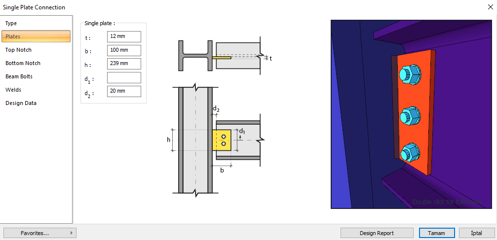
A single plate connection is a non-moment transfer connection (hear connection) that is bolted to the body of the profile and welded to the support. Bolt control, weld control and plate control are performed automatically according to the placement of the elements of the connection. Connection design with single plate is made automatically according to the Design AISC 360-16 (ASD and LRFD) regulations and the connection report is generated.
In the connection calculation with single plate, distance control between bolts, horizontal and vertical edge distance control, weld thickness control, mounting stability controls are made as geometry control. As a strength control, checks are made for shear in beam bolts, crushing in beam and plate bolt holes, plate shear yielding, beam and plate shear failure, plate block slip, plate bending buckling, plate bending yield, support welding strength.
Download ideCAD for Connection Design with AISC 360-16
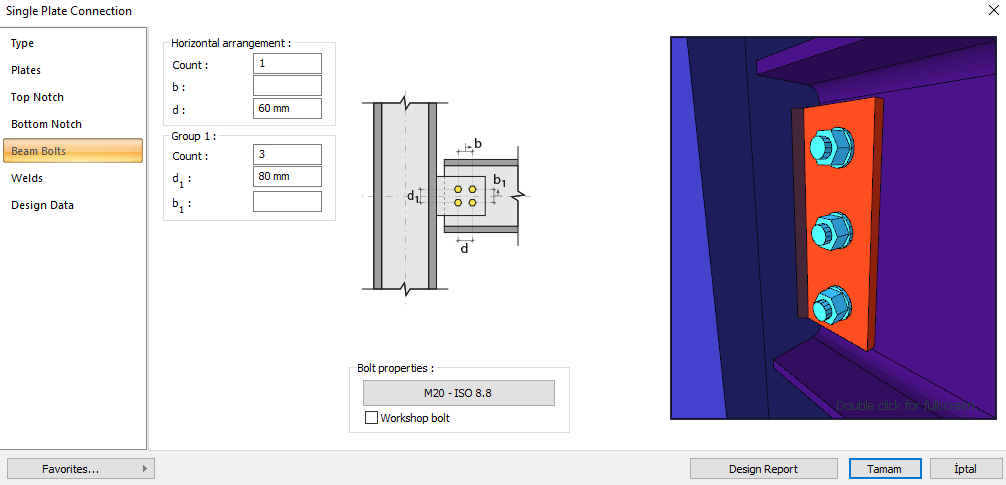
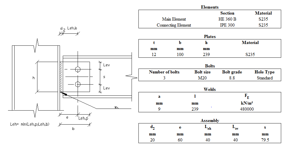
Connection Geometry
Geometry Checks
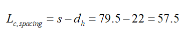
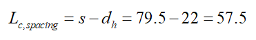
Spacing between bolts
|
|
ÇYTHYEDY 13.3.6 |
|
|
|
|
79.5 mm |
|
|
|
|
20 mm |
s =79.5 mm > smin = 3*20=60 mm |
√ |
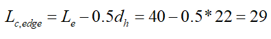
Horizontal Edge Distance
|
|
ÇYTHYEDY 13.3.7 |
|
|
|
|
40 mm |
L eh ≥ 2d = 2 * 20 = 40 mm conformity check for application |
√ |
|
|
26 mm |
Minimum distance check according to Table 13.9 |
√ |
Vertical Edge Distance
|
|
ÇYTHYEDY 13.3.7 |
|
|
|
|
40 mm |
L eh ≥ 2d = 2 * 20 = 40 mm conformity check for application |
√ |
|
|
26 mm |
Minimum distance check according to Table 13.9 |
√ |
Weld Thickness
|
|
ÇYTHYEDY 13.3.7 |
|
|
|
|
9 mm |
|
√ |
|
|
3.5 mm |
Table 13.4 |
√ |
Erection Stability
|
|
ÇYTHYEDY 13.3.7 |
|
|
|
L |
239 mm |
|
|
|
|
248.6 mm |
L=239 > 248.6/2=124.3 mm |
√ |
Strength Checks
Bolt Shear at Beam
-
Calculation is made using Elastic method, one of the methods selected in the steel analysis settings tab. For the details of this calculation, AISC Manual 14th 7-8 is used as a reference.
-
In this calculation, the operation is performed on half of the symmetry axis and it is calculated to form a force pair with the required force.
|
|
|
|
|
|
|
|
|
|
|
|
|
Required |
Available |
Ratio |
Control |
|---|---|---|---|
|
32,601 kN |
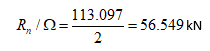
56,549 kN |
0.577 |
√ |
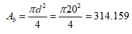
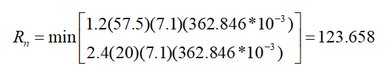
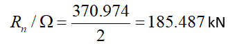
Bolt Bearing on Beam
|
|
20+2=22 mm |
|
|
|
|
|
|
|
|
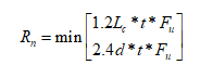
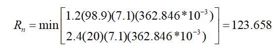
ÇYTHYEDY 13.3.13 Equation 13.14a and13.14b |
|
|
|
|
|
|
|
|
|
|
|
|
|
|

|
|
|
|
|
|
|
Required |
Available |
Ratio |
Control |
|---|---|---|---|
|
64.748 kN |
185,487 kN |
0.349 |
√ |
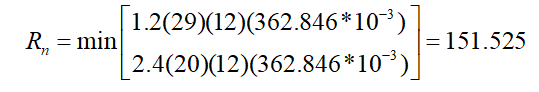
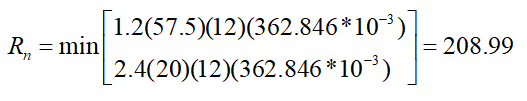
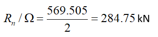
Bolt Bearing on Plate
|
|
20+2=22 mm |
|
|
|
|
|
|
|
|
ÇYTHYEDY 13.3.13 Equation 13.14a and13.14b |
|
|
|
|
|
|
|
|
|
|
|
|
|
|

|
|
|
|
|
|
|
Required |
Available |
Ratio |
Control |
|---|---|---|---|
|
64.748 kN |
284.75 kN |
0.227 |
√ |
Plate Shear Yield
|
|
|
|
|
|
235.359 N/mm2 |
|
|
|
|
ÇYTHYEDY 13.17 |
|
|
|
|
|
Required |
Available |
Ratio |
Control |
|---|---|---|---|
|
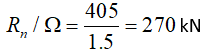
64.748 kN |
270 kN |
0.240 |
√ |
Beam Shear Rupture
|
|
|
|
|
|
362.846 N/mm2 |
|
|
|
|
ÇYTHYEDY 13.18 |
|
|
|
|
|
Required |
Available |
Ratio |
Control |
|---|---|---|---|
|
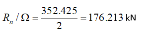
64.748 kN |
176.213 kN |
0.367 |
√ |
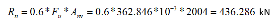
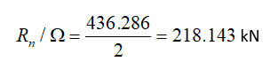
Plate Shear Rupture
|
|
|
|
|
|
362.846 N/mm2 |
|
|
|
|
ÇYTHYEDY 13.18 |
|
|
|
|
|
Required |
Available |
Ratio |
Control |
|---|---|---|---|
|
64.748 kN |
218.143 kN |
0.297 |
√ |
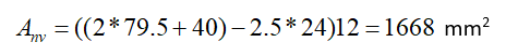
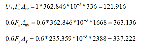
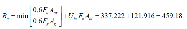
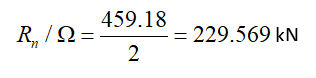
Block Shear in Plate
|
|
|
|
|
|
|
|
|
|
|
|
|
|
235.359 N/mm2 |
|
|
|
362.846 N/mm2 |
|
|
|
one |
|
|
|
|
|
|
|
|
ÇYTHYEDY 13.19 |
|
|
|
|
|
Required |
Available |
Ratio |
Control |
|---|---|---|---|
|
64.748 kN |
229.569 kN |
0.282 |
√ |
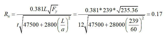
Plate Flexural Buckling
|
|
235.359 N/mm2 |
|
|
t |
12 mm |
|
|
a |
60 mm |
|
|
L |
239 mm |
|
|
λ |
|
|
|
Required |
Available |
Control |
|---|---|---|
|
≤0.70 |
0.17 |
√ |
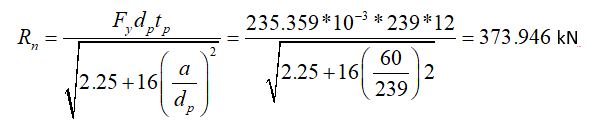
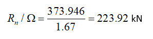
Plate Flexural Yield
|
|
239 mm |
|
|
|
235.359 N/mm2 |
|
|
|
12 mm |
|
|
|
60 mm |
|
|
|
|
|
|
|
|
|
|
Required |
Available |
Ratio |
Control |
|---|---|---|---|
|
64.748 kN |
223.92 kN |
0.289 |
√ |
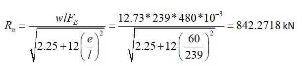
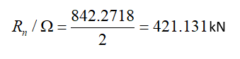
Weld Strength at Support
|
in |
12.73 mm |
|
|
|
480 N/mm2 |
|
|
l |
239 mm |
|
|
is |
60 mm |
|
|
|
|
|
|
|
|
|
|
Required |
Available |
Ratio |
Control |
|---|---|---|---|
|
64.748 kN |
421.131 kN |
0.154 |
√ |
Download ideCAD for Connection Design
Next Topic
Related Topics