
-
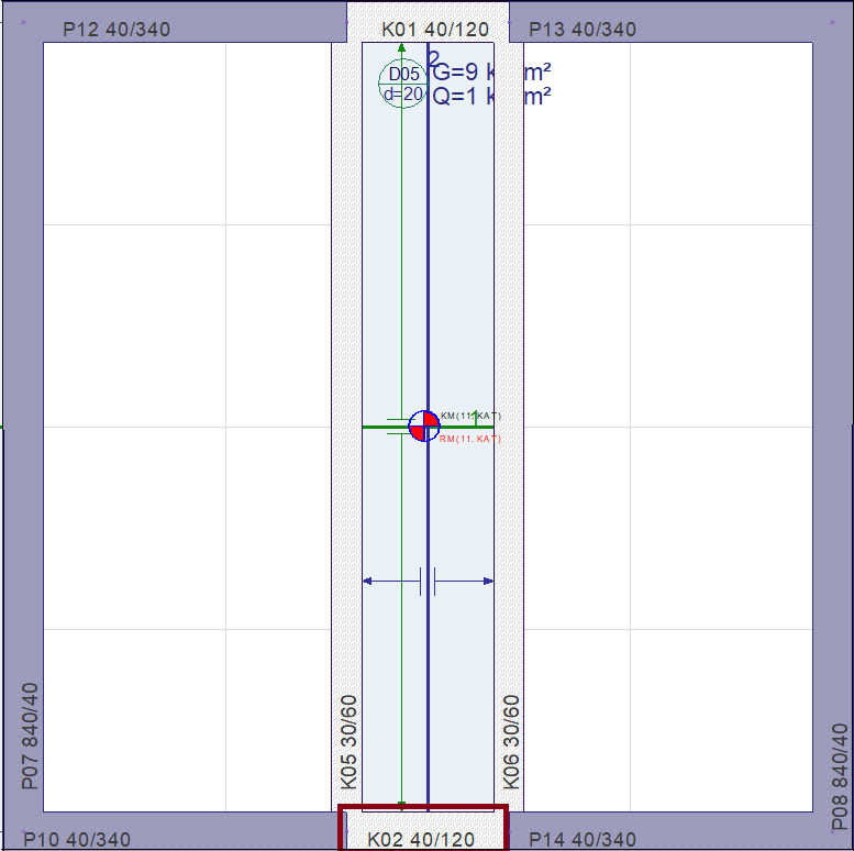
For example, the coupling beam on the 11th floor of the building will be calculated.
-
If any of the conditions specified in TBDY 7.6.8.2 are not met, the shear reinforcement calculation of coupling beams is made according to TBDY 7.4.5.
-
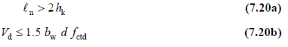
In manual control;
ln = 160 <2h k = 2 * 120 = 240 ꭓ
Vd = 965.46 kN ≤ 1.5 * 40 * 120 * 1380 = 994 kN
Since one of the conditions does not meet, the shear reinforcement calculation of coupling beams will be made according to TBDY 7.6.8. TBDY 7.6.8 points to 7.4.5.
-
Shear force acting on coupling beams should not exceed the following upper limit. (TBDY 7.6.8.3) The calculation was made with equation 7.22 below.
Vd = 965.46 kN ≤ 0.85 * bw * d * √fck = 0.85 * 0.4 * 1.2 * √35 = 2414 kN √
-
According to TBDY 7.6.8.2, the total area of reinforcement in each crossbar beam is calculated with equation 7.21.
-
The total number and diameter of reinforcement selected for a cross reinforcement bundle is 8Φ25.
-
In addition to diagonal reinforcements, earthquake hoops specific to coupling beams will be calculated in accordance with TBDY 7.6.8.2b. At the same time, the minimum amount of stirrups and horizontal reinforcements stipulated in TS 500 will be installed.
-
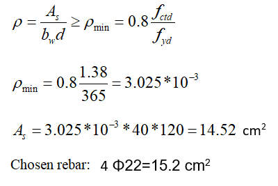
Minimum tensile reinforcement ratio in beams according to TS 500:
-
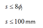
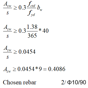
Stirrup calculation in accordance with TBDY 7.6.8.2b
-
Stirrup calculation as per TS 500
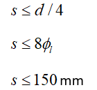
-
Selected stirrup spacing s = 90 mm
-
The reinforced concrete configuration feature is used to control the reinforcement placement in the program interface. The image below is taken from this tab.
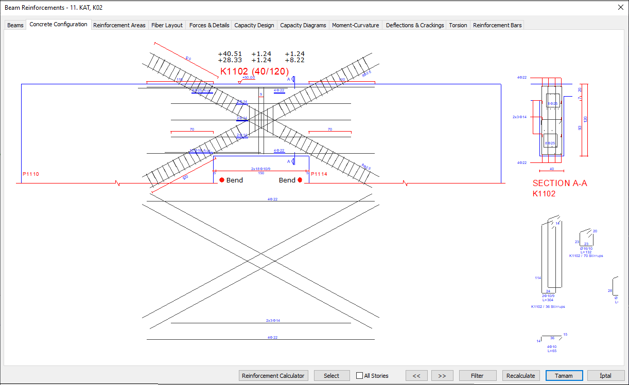
-
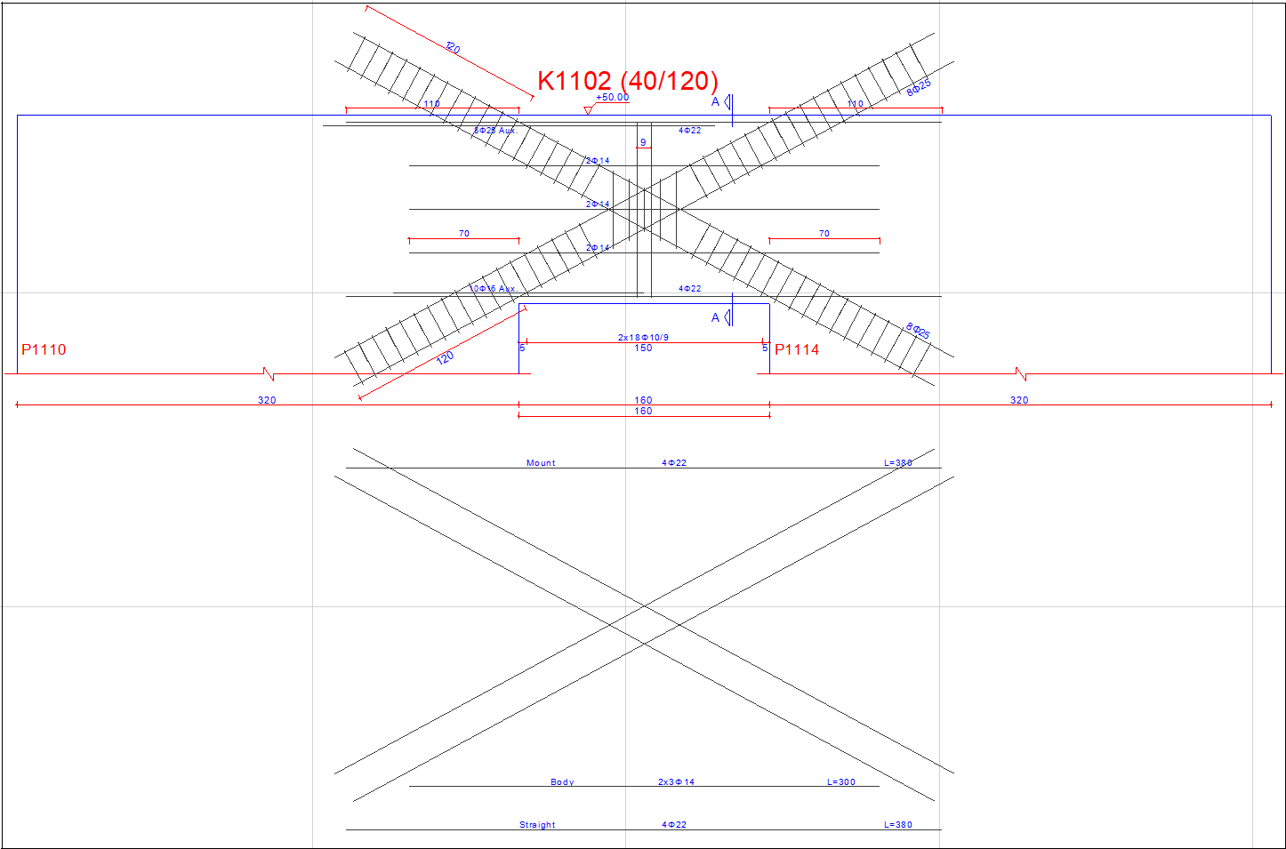
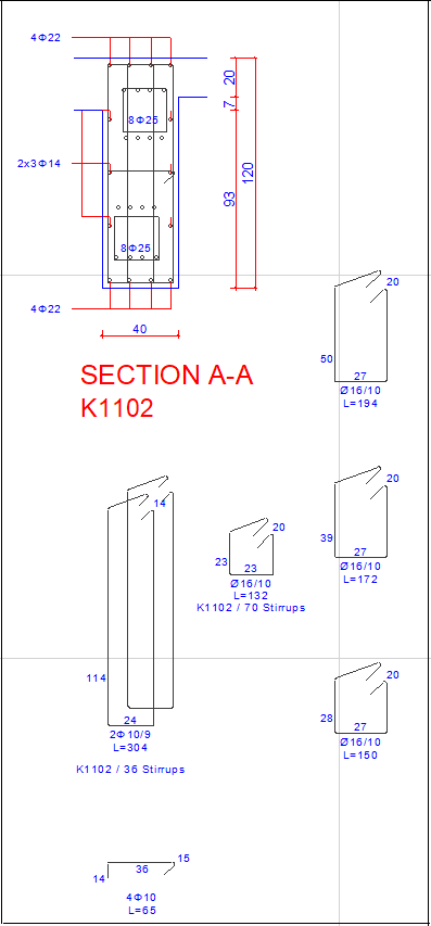
When the drawings are taken, the tie beam, bundle reinforcement and stirrup drawings are as follows:
Next Topic