
Pile drawings, whose calculation axes have been defined and analyzed, can be prepared with the Pile Drawings command.
Location of the Pile Drawings Command
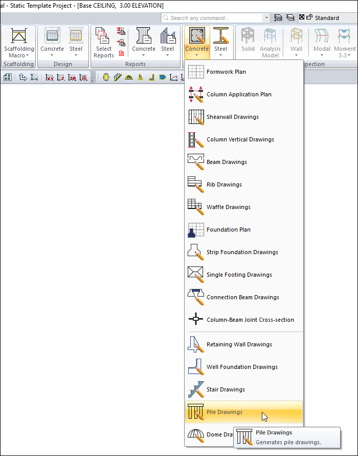
You can access it under the ribbon menu Concrete tab, Create Drawing heading.
Usage Steps
-
Click the Pile Drawings icon.
-
The drawing properties dialog will open. If there is a different situation in this dialog, change the parameters related to the drawing.
-
When you click the OK button, the pile drawing will be created.
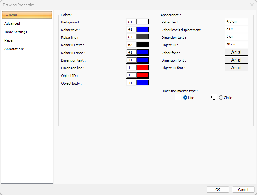
General Tab
|
Specifications - Colors |
|
Background color Sets the background color. When the color box is clicked, the appropriate color is selected from the window that opens. |
|
Rebar text Sets the color of the rebar text. When the color box is clicked, the appropriate color is selected from the window that opens. |
|
Rebar line Sets the color of the reinforcement line. When the color box is clicked, the appropriate color is selected from the window that opens. |
|
Rebar ID text Adjusts the color of the rebar ID text. When the color box is clicked, the appropriate color is selected from the window that opens. |
|
Rebar ID circle Adjusts the color of the rebar ID circle. When the color box is clicked, the appropriate color is selected from the window that opens. |
|
Dimension text Sets the dimension text color. When the color box is clicked, the appropriate color is selected from the window that opens. |
|
Dimension line Sets the dimension line color. When the color box is clicked, the appropriate color is selected from the window that opens. |
|
Object ID Sets the color of the object ID. When the color box is clicked, the appropriate color is selected from the window that opens. |
|
Object body Sets the color of the object body. When the color box is clicked, the appropriate color is selected from the window that opens. |
|
Specifications - Appearance |
|
Rebar text The height of the rebar text is entered. |
|
Rebar levels displacement The distance between the two rebar texts is entered. |
|
Dimension text The height of the dimension text is entered. |
|
Object ID The height of the object ID is entered. |
|
Rebar font The rebar font is selected. |
|
Dimension font Dimension font is selected. |
|
Object ID font Object ID font is selected. |
|
Dimension marker type The dimension marker type is selected. |
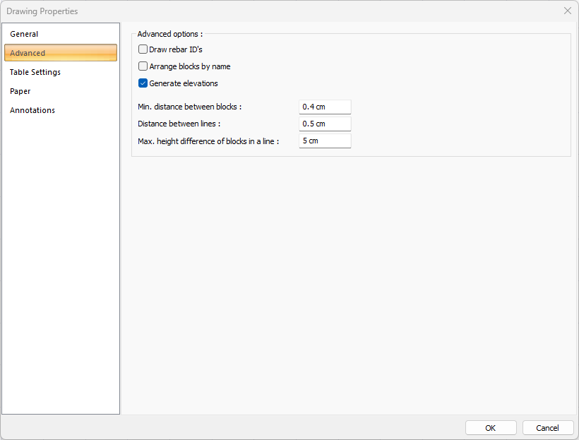
Advanced Tab
|
Specifications |
|---|
|
Draw rebar ID’s If checked, rebar ID’s are shown in the drawings. If not checked, it will not be displayed. |
|
Arrange blocks by name In the expansions, the objects are marked if they want to be placed according to the element names while placing the layout on the layout. If not marked, the expansions are placed according to the principle of the most economical use of the layout. The name is ignored. Names can be mixed. Object names; For example, if beam is mentioned, they are names such as K101, K104 etc. The expansion is beam opening, foundation opening, rib opening, etc. |
|
Generate elevations If checked, elevations are shown in the drawings. If not checked, it will not be displayed. |
|
Min. distance between blocks Minimum horizontal distance between blocks is entered. The block is each opening itself, with its rebars, sections and dimensioning. |
|
Distance between lines Minimum vertical distance between blocks is entered. The block is each opening itself, with its rebars, sections and dimensioning. |
|
Max. height difference of blocks in a line The maximum height difference of each block in the row (vertical direction) is entered. If the difference between the height of the block to be placed and the height of the previously placed block is smaller than the value entered on this line, the layout is made. If it is large, no settlement is made. It is left to the next row. The block is each opening itself, with its rebars, sections and dimensioning. |
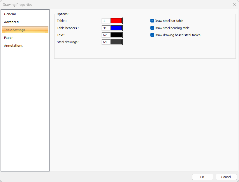
Table Settings Tab
|
Specifications |
|---|
|
Table Sets the color of the table. When the color box is clicked, the appropriate color is selected from the window that opens. |
|
Table header Sets the color of the table headers. When the color box is clicked, the appropriate color is selected from the window that opens. |
|
Text Sets the color of table text. When the color box is clicked, the appropriate color is selected from the window that opens. |
|
Steel drawings Sets the color of the rebar drawing. When the color box is clicked, the appropriate color is selected from the window that opens. |
|
Draw steel bar table If marked, the rebars are divided into types and a table is created indicating the number, diameter, length, type and weight, and the rebar meter is shown in the drawing. |
|
Draw steel bending table If checked, the rebars are divided into bending types and a table is created indicating the number, diameter, length and type, and the bend is shown in the drawing. |
|
Draw drawing based steel tables If it is marked, in the drawings in more than one paper, the quantity is prepared separately for the drawing in each paper and its total is given in the last paper. If unchecked, the total quantity is shown on each paper. For example, let's say a beam spread of 3 papers. If the option is selected, the quantity of only the beams in that section in the 1st section, the meter length of the beams on the 2nd section in the 2nd section, and the total of all the beams on the 1st, 2nd and 3rd sections in the 3rd section are given as meter lengths. If the option is not selected, in the 1st, 2nd and 3rd sheets 1., 2. , 3. All beams in the layout are shown. |
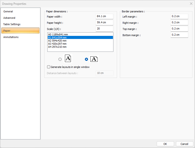
Paper Tab
|
Specifications |
|---|
|
Paper width As well as selecting the standard paper sizes, any paper width value can also be entered. |
|
Paper height Standard paper sizes can also be selected, and any paper size value can be entered. |
|
Scale (1/X) In what scale the expansions will be drawn, that value is entered. |
|
Standard paper sizes Standard paper sizes are listed. The layout size can be selected from the list, as well as the layout dimensions can be determined by entering the width and height values. |
|
Vertical/Horizontal use It is determined whether the layout will be used horizontally or vertically. |
|
Generate layouts in single window By selecting the option, layouts are created in a single window. |
|
Distance between layouts The distance between the layouts to be created side by side is entered. |
|
Left margin The distance of the layout border from the axis border to the left side is entered. |
|
Right margin The distance from the axis border to the right side of the layout border is entered. |
|
Top margin Enter the distance from the axis border to the top side of the layout border. |
|
Bottom margin The distance from the axis border to the bottom side of the paper border is entered. |
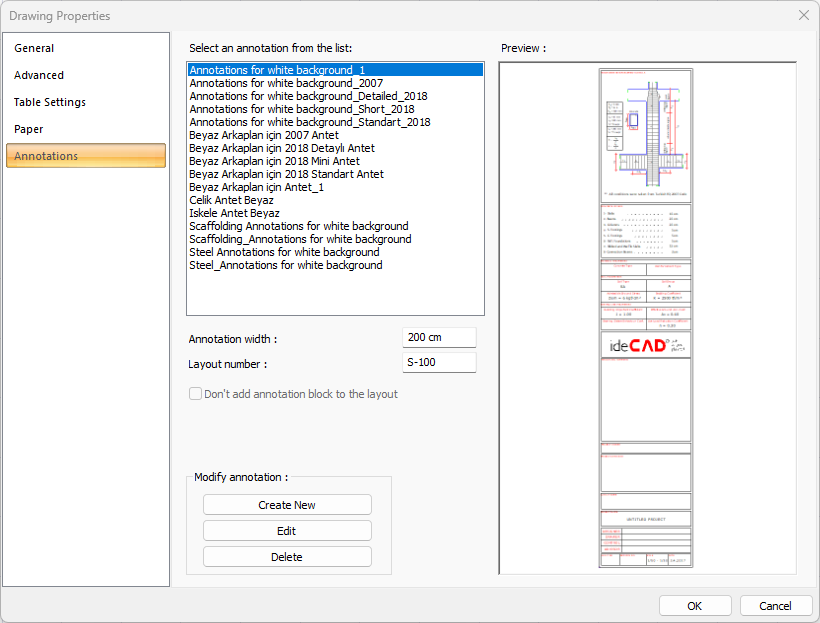
Annotations Tab
|
Specifications |
|---|
|
Select an annotation from the list 
Defined annotations are listed. |
|
Preview 
There is a preview of the annotation selected from the list. |
|
Annotation width Annotation width is determined. |
|
Layout number The layout number is determined. |
|
Create New The new annotation is created. |
|
Edit The annotation is edited. |
|
Delete The annotation is deleted. |
|
Don’t add annotation block to the layout If it is checked, annotation will not be added to the layouts. |
Next Topic