
|
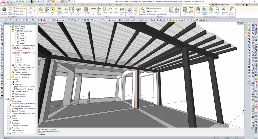
After analyzing the results of the project whose Analysis+Design has been done, steel connections can be modeled. For steel connection modeling, the locations of the elements can be changed accordingly and Analysis+Design is repeated. |
Steel members are to be arranged for modeling steel connections.
-
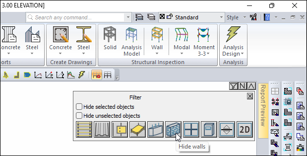
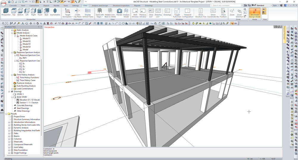
Click the Filter command in the perspective view window.
-
Hide wall objects in perspective view by clicking the Hide Walls button.
-
Close the filter window.
-
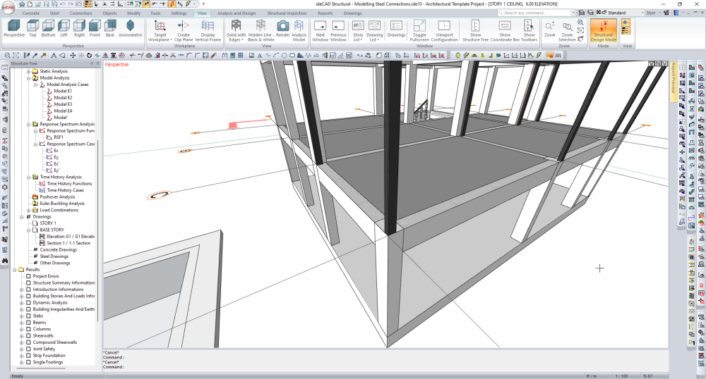
Switch to Full Screen in the perspective view window.
-
Open the STORTY 1 CEILING page.
-
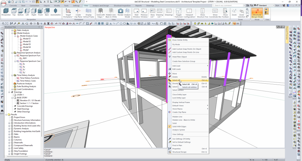
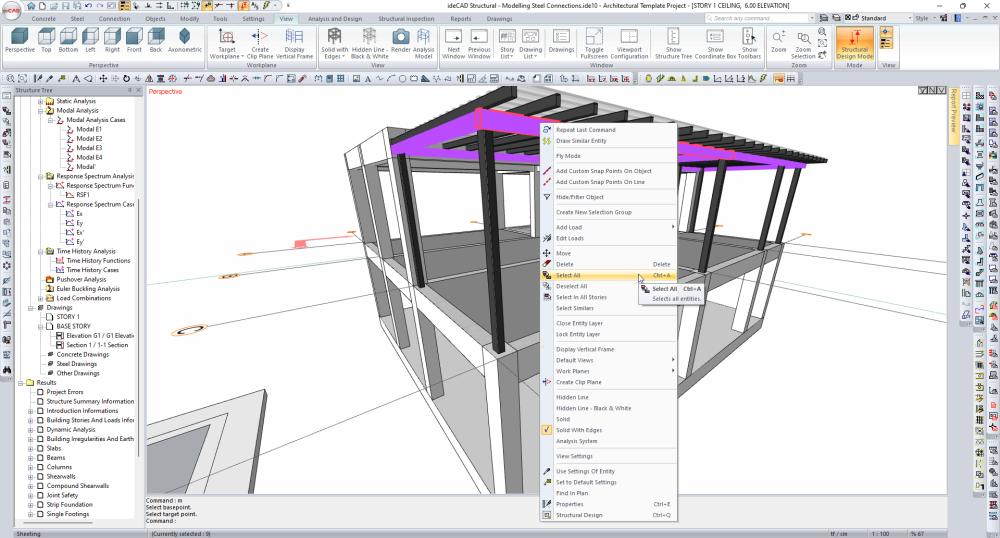
Right click on any steel column and open the menu.
-
Select all steel columns by clicking the Select All command.
-
Right click on any steel column and open the menu.
-
Click the Properties command.
-
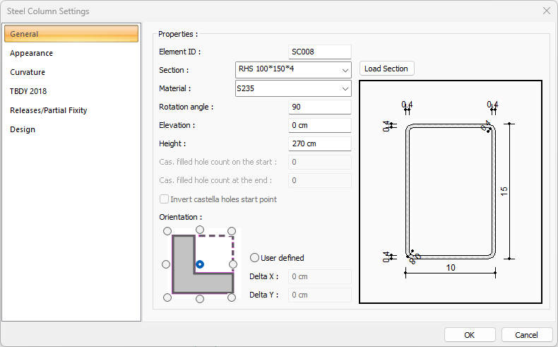
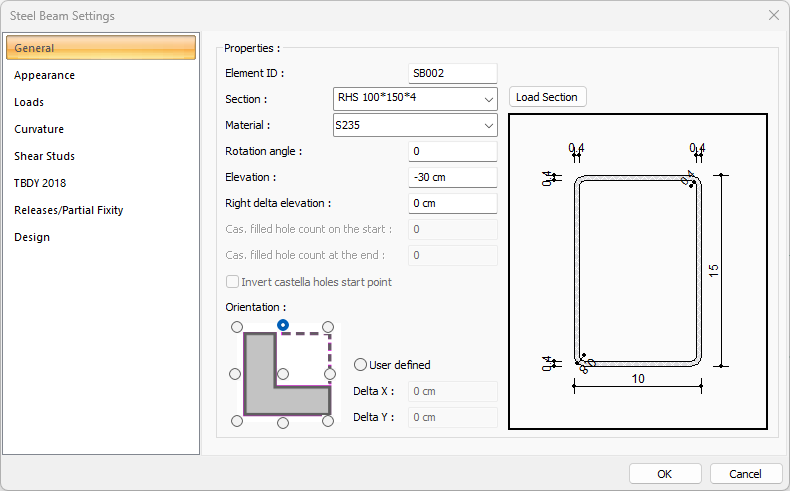
The steel column settings dialog will open.
-
Enter the rotation angle value as 90 degrees
-
Mark Orientation as middle.
-
Click the OK button to close the dialog.
-
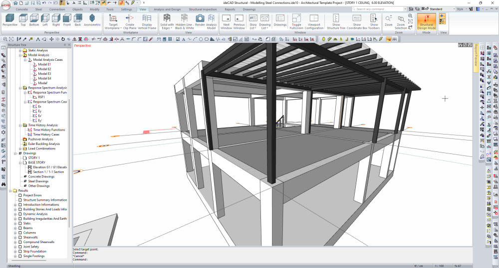
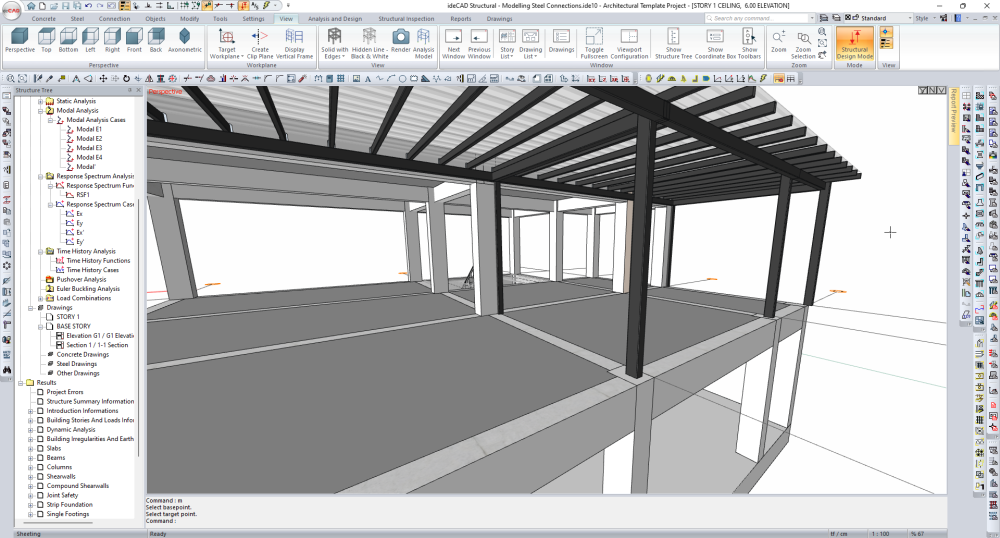
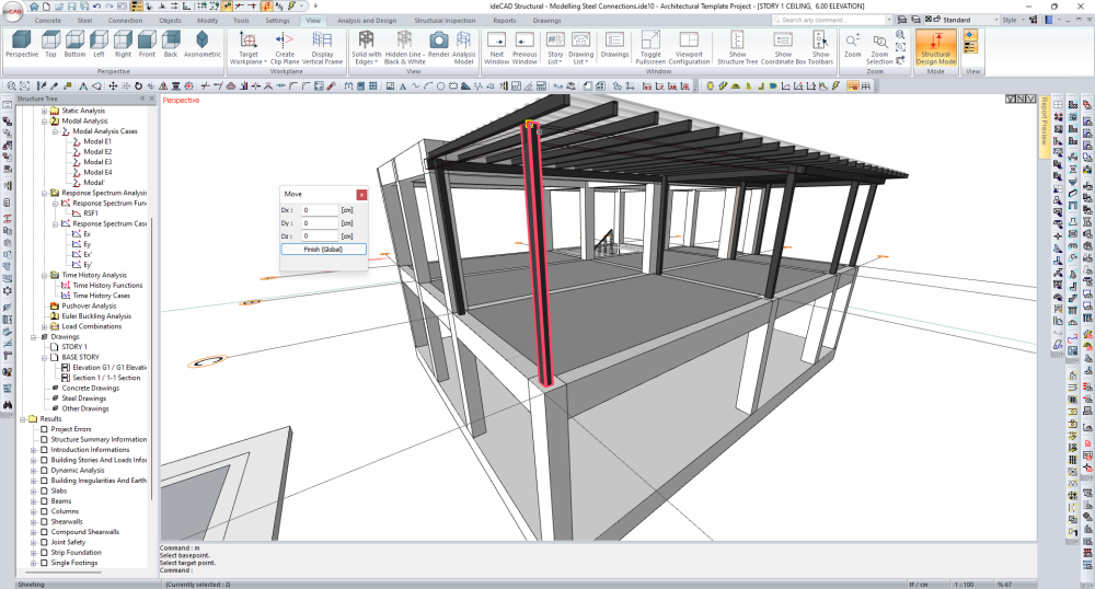
Select the steel column located at the D-1 axis intersection.
-
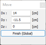
Click the Move command and select the steel column node.
-
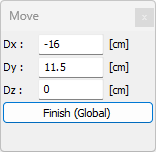
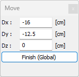
Enter -16 cm in the Dx line, 11.5 cm in the Dy line and click the finish button.
-
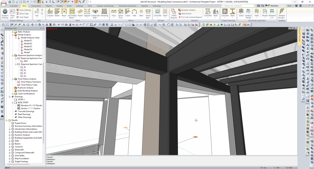
The position of the steel column will change and it will become possible to define the connection.
-
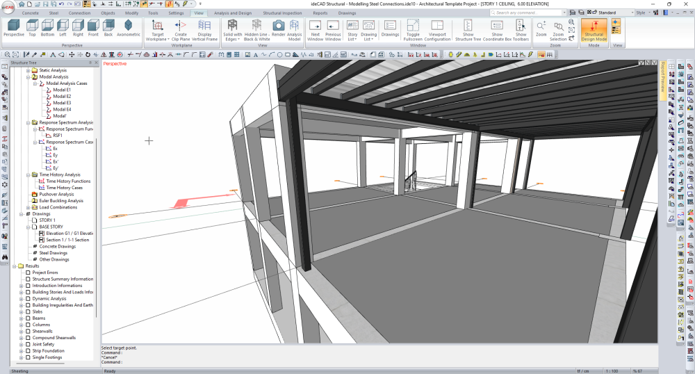
Select the steel column located at the C-1 axis intersection.
-
Click the Move command and select the steel column node.
-
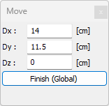
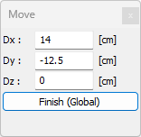
Enter 14 cm in the Dx line, 11.5 cm in the Dy line and click the finish button.
-
Select the steel columns located at the D-2 and D-3 axis intersection.
-
Click the Move command and select the steel column node.
-
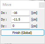
Enter -16 cm in the Dx line, -12.5 cm in the Dy line and click the Finish button.
-
Select the steel columns located at the C-2 and C-3 axis intersection.
-
Click the Move command and select the steel column node.
-
Enter 14 cm in the Dx line, -12.5 cm in the Dy line and click the finish button.
-
Select the steel column located at the D-4 intersection.
-
Click the Move command and select the steel column node.
-
Enter -16 cm in the Dx line, -11.5 cm in the Dy line and click the Finish button.
-
Select the steel column located at the C-4 intersection.
-
Click the Move command and select the steel column node.
-
Enter 14 cm in the Dx line, -11.5 cm in the Dy line and click the Finish button.
-
Right click on any beam and open the menu.
-
Select all steel beams by clicking the Select All command.
-
Right click on any steel beam and open the menu.
-
Click the Properties command.
-
From the Steel Beam Settings dialog that opens, select the layout as mid-top.
-
Click the OK button to close the dialog.
-
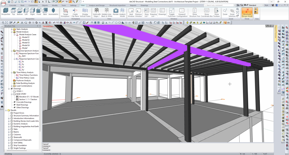
Select the steel beams attached to the steel column at the D-1 axis intersection.
-
Click the node at the intersection of the selected beams.
-
Then click on the column node.
-
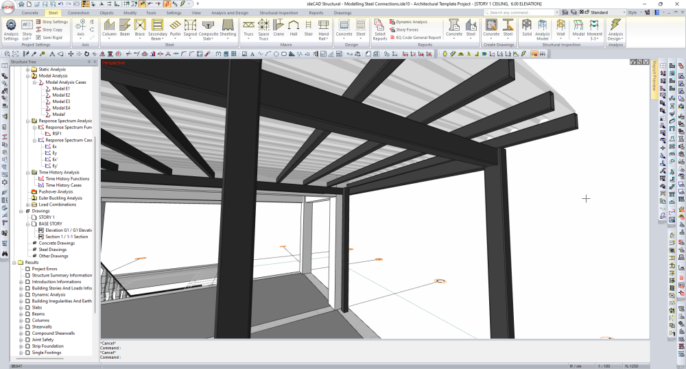
The node points of the steel beams will be moved to the column node.
-
Select the steel beams attached to the steel column at the C-1 axis intersection.
-
Click the node at the intersection of the selected beams.
-
Then click on the column node.
-
Connect the steel beam nodes at the D-2 axis intersection to the column node.
-
Connect the steel beam nodes at the C-2 axis intersection to the column node.
-
Connect the steel beam nodes at the D-3 axis intersection to the column node.
-
Connect the steel beam nodes at the C-3 axis intersection to the column node.
-
Connect the steel beam nodes at the D-4 axis intersection to the column node.
-
Connect the steel beam nodes at the C-4 axis intersection to the column node.
-
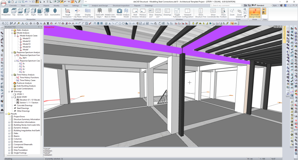
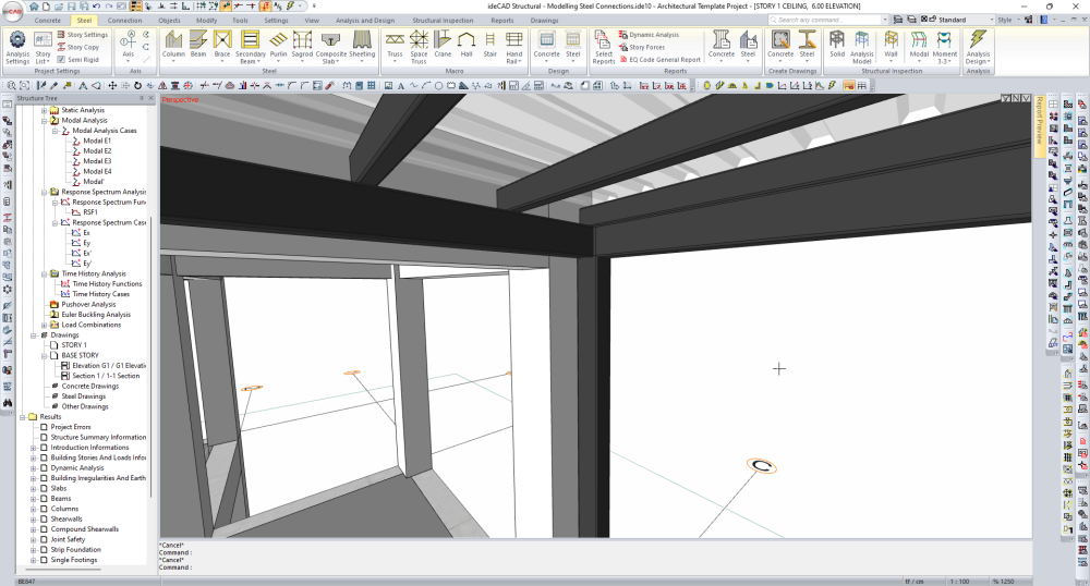
Arrangement of steel columns and beams has been completed for connections.
Follow the steps of the video below.
Next Tutorial