
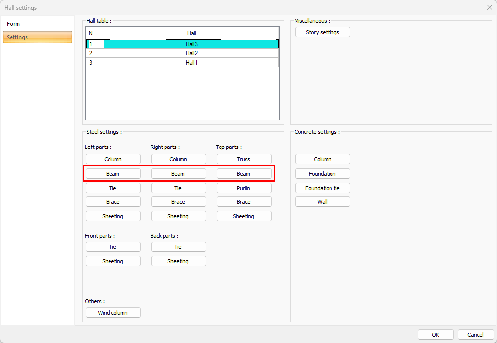
The hall steel beam settings are changed by clicking the Steel Beam button from the hall settings dialog settings tab. Steel beam settings are made separately for the right, left and upper part of the hall.
Location of Steel Beam Settings
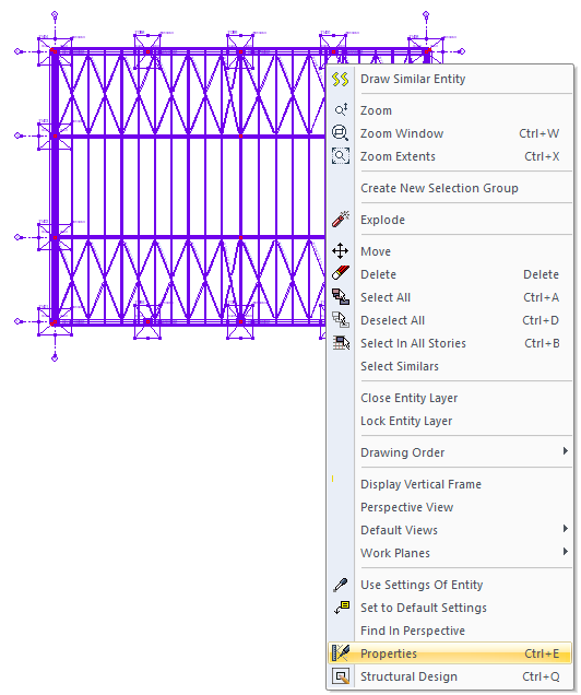
Select the hall where you want to change the steel beam settings and click the right mouse button. Click the Properties line from the right click menu that opens.
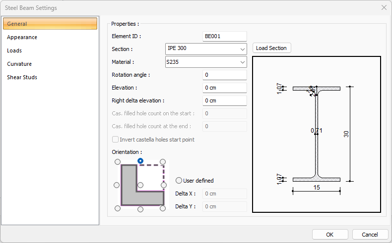
General Tab
|
Specifications |
|---|
|
Element ID It is the name of the beam that appears in the plan, reports and drawings. |
|
Section The profile used appears. By clicking the list, one of the previously defined profiles can be selected or a new profile can be selected from the dialog that opens when the Load Section button is clicked. |
|
Load section By accessing the ready section library, a list of American and European finished rolling sections is reached and a selection is made from the list. |
|
Material The material for the steel column is selected. |
|
Rotation angle It is the value that determines the angle of the beam with respect to the beam axis. According to the given angle value, the beam is drawn by rotating around its axis. |
|
Elevation It is the value determining the height of the steel beam from the floor base. Positive elevation raises the beam. |
|
Right delta elevation It is used to make inclined beams. It is the elevation value of the right end of the beam relative to the floor base. |
|
Cas. filled hole count on the start/at the end For honeycomb profiles, it is the number that determines how many holes the honeycomb spaces will start from the beginning and the end. The honeycomb beams will be full up to the given number. |
|
Orientation 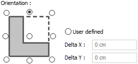
These are the options that determine the delta of the beam in the plan according to its axis. It provides adjustment of 9 different offset in the placement of the beam on the axis. Select the relevant option in the diagram shown according to the beam section or enter any numerical value in the user-defined section. |
|
Schematic drawing 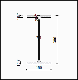
The schematic drawing and dimensions of the selected section are shown. |
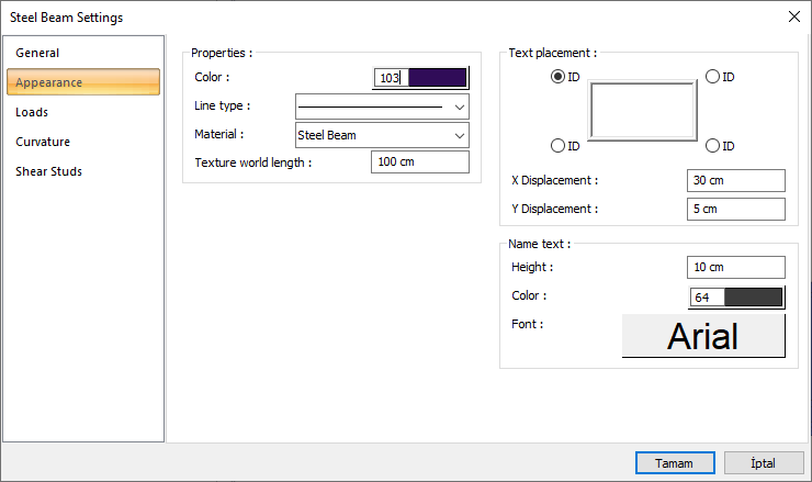
Appearance Tab
|
Specifications |
|---|
|
Color It is the color of the beam's border lines. It scrolls on the color palette that is opened by clicking and holding down the left mouse button. The button is released when the desired color is reached. The color box turns into the selected color. |
|
Line type Line type of the line forming the beam is selected in the plan. Clicking the down arrow buttons to the right of the boxes opens the list of line types. From this list, the desired line type is selected by clicking with the left mouse button. |
|
Material The material to be covered on the solid model of the beam is selected. The beam is covered with the selected material and displayed in the solid model like this. |
|
Texture world length Texture length is entered. For example; If 1 meter is entered, the selected material texture is taken as 1 meter and covered on the selected object. Considering that the texture is in the form of a square, the object surfaces are covered with 1x1 textures arranged side by side. |
|
Text placement 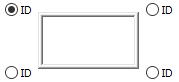
The position where the beam name will be written relative to the beam is determined according to the figure in the dialog. The program will place the name of the element according to the position selected when the column was created. |
|
X/Y Displacement X and Y coordinates are entered according to the upper right corner of the beam name. If the dimension X value is positive, the dimension text shifts to the left, if it is negative, it shifts to the right. If the dimension Y value is positive, the dimension text will scroll up, and if it is negative, it will scroll down. |
|
Name text 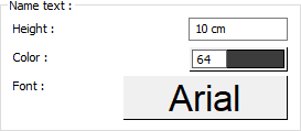
The height of the beam name text is entered. The color box is slid over the color palette that is opened by clicking and holding down the button with the left mouse button. The button is released when the desired color is reached. The color box turns into the selected color. If clicked together with the Shift key, the pen thickness of the relevant color can be adjusted. If the button below is clicked, the Font Settings dialog opens. Beam Name Text, font type is set from this dialog. |
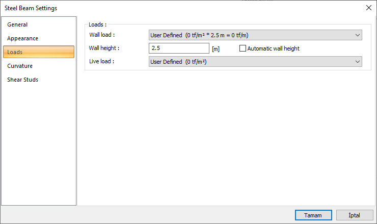
Loads Tab
|
Specifications |
|---|
|
Wall load 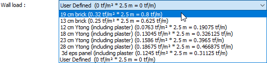
The appropriate wall load is selected from the list. The wall loads in the list are those defined in the load library. If you want to specify a value other than these values as wall load, the user defined line is selected from the list and the appropriate value is given. The value should be defined as the weight per 1 meter of the wall above the beam. |
|
Wall height The height of the wall can be determined on request. The length of the clean wall should be subtracted from the story height and the beam heights in the story. If the wall height is determined by the user, the wall load will be calculated according to this height and the determined wall unit weight. |
|
Automatic wall height If the option is selected, the program automatically calculates the clean wall length by subtracting the beam height from the story height according to the set offset of the relevant beams and uses this height when calculating the fixed load. |
|
Live load 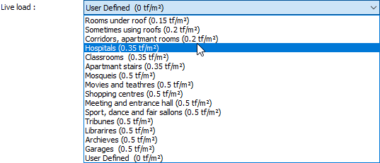
It is the extra additional live load that can be defined on the beam. It can be used if extra load is defined outside the system to the beam. The appropriate value is selected from the list. The loads in the list are those defined in the load library. If you want to specify a value other than these values as load, the user defined line is selected from the list and the appropriate value is given. |
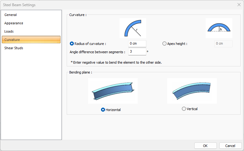
Curvature Tab
|
Specifications |
|---|
|
Radius of curvature 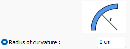
The radius value is given according to the center of the arc segment based on the height of the column. Negative value will create curvature to the other side. |
|
Apex height 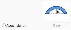
The height value is given according to the middle height of vault element, middle axis height of curvature element. |
|
Angle difference between segments The precision angle used when creating curvature. As sensitivity increases, processing speed decreases. |
|
Bending plane 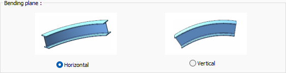
It is determined whether the curvature will be horizontal or vertical. |
Shear Studs Tab
|
Specifications |
|---|
|
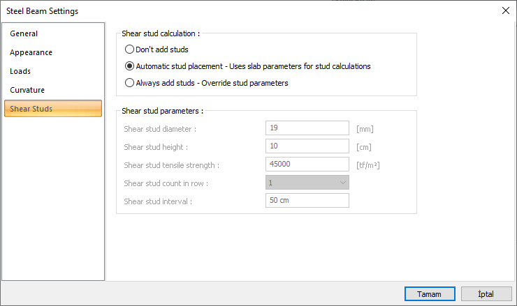
Don’t add studs If marked, the shear stud is not modeled under any circumstances. |
|
Automatic stud placement If checked, the shear stud parameters in the slab settings are used in the modeling made using steel slab - composite options. |
|
Always add studs If it is marked, the shear stud placement is done by taking the information from the 4 numbered slip nail parameters. |
|
Shear stud parameters 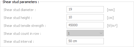
It becomes active if the always add shear stud option is selected, and it is used to determine parameters such as diameter, height, spacing, tensile strength. |
Next Topic