
The sub region command is certain surfaces on the terrain that fit the terrain slope. In the architectural project design, surfaces that want to define different materials such as walkways and paths are created as sub-regions.
Location of the Sub Region Command
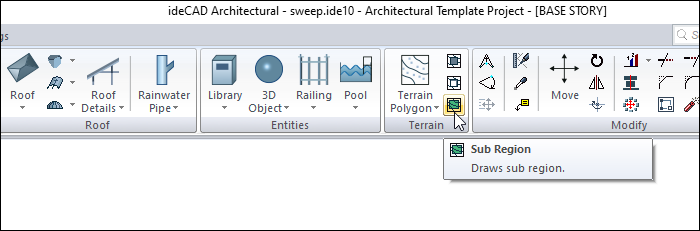
In the Architectural Program
You can access it under the ribbon menu Home tab Terrain title.
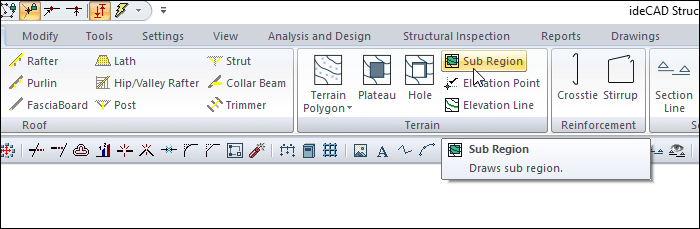
In Structural Program
You can access it under the ribbon menu Objects tab Terrain title.
Usage Steps
-
Click the Sub Region icon in the ribbon menu .
-
Next to the terrain toolbar, another toolbar named Path Segments will appear on the screen .
-
The Path Segments toolbar contains icons for drawing straight, circular and curved contours. These icons are used according to the needs while defining the sub region.
-
Move the mouse over the terrain you defined earlier.
-
Click on the corners of the sub region element in the drawing screen.
-
The process will be completed when you define the contour and reach the point where you started.
|
Usage step |
|---|
|
Terrain before sub region is created 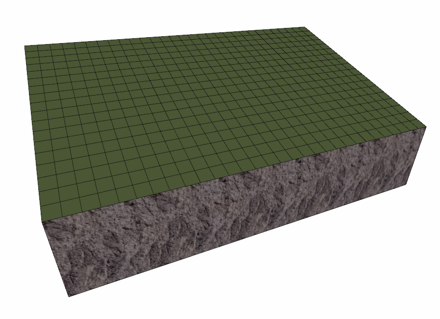
|
|
Determining the first point of the closed polygon to be created for the sub region 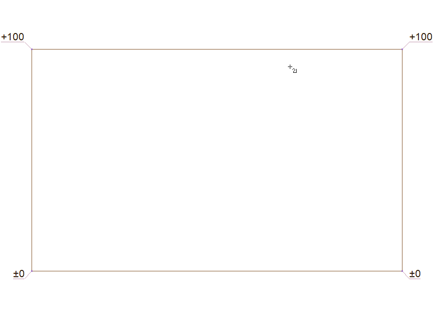
|
|
Determining the second point of the closed polygon 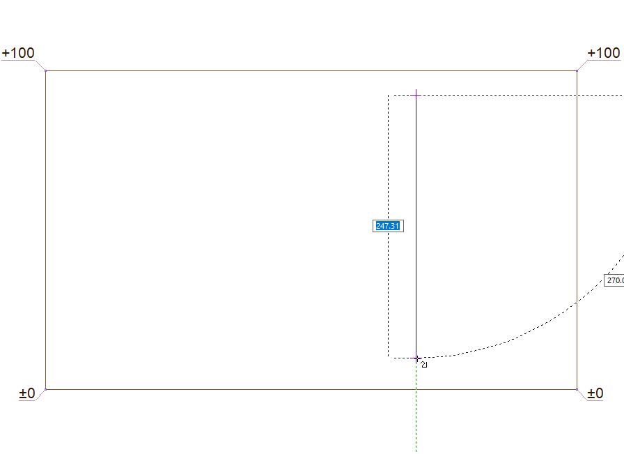
|
|
Determining the third point of the closed polygon 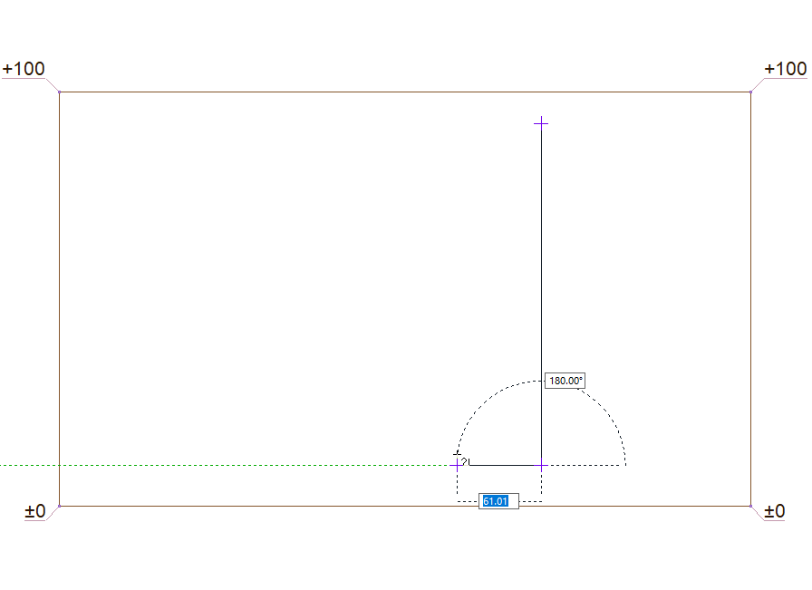
|
|
Determining the fourth point of the closed polygon 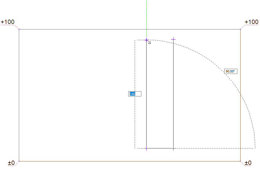
|
|
Determining the end point of the closed polygon 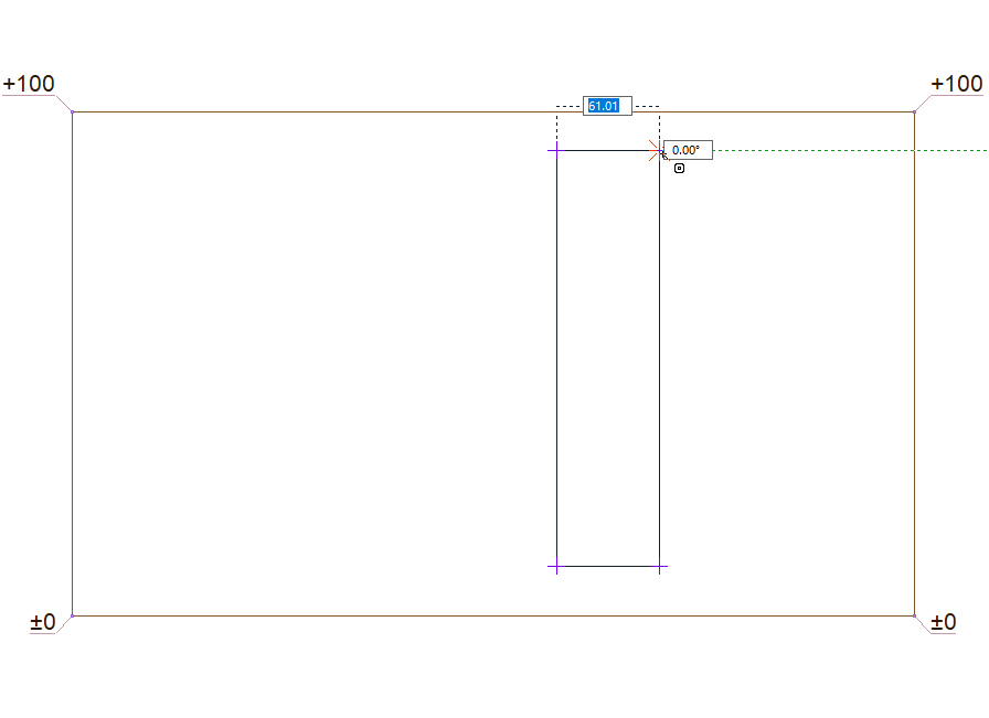
|
|
Formation of the sub region 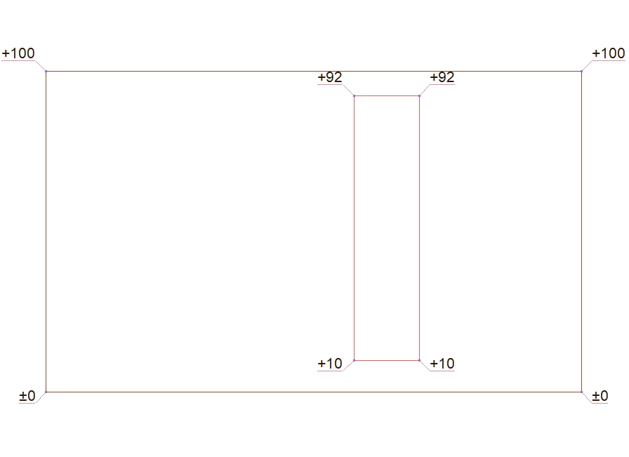
|
|
Terrain after sub region has been created 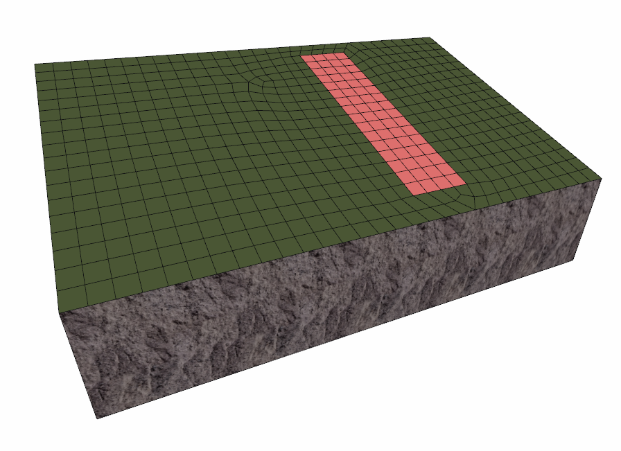
|
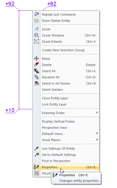
Location of Sub Region Settings Dialog
Select the sub region you want to enter its settings, click the right button of the mouse and click the Properties line from the menu that opens .
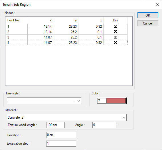
Sub Region Settings
|
Specifications |
|---|
|
Nodes 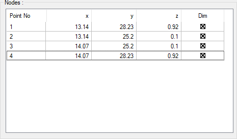
The coordinates of the elevation points placed are given. It is not intervened. |
|
Color The drawing color of the sub region line in the plan. When the color box is clicked, the appropriate color is selected from the window that opens. |
|
Line style The line type of the sub region line in the plan is selected. Clicking the down arrow buttons to the right of the boxes opens the list of line types. From this list, the desired line type is selected by clicking with the left mouse button. |
|
Material You can select the material of the sub region surface by clicking it from the list. |
|
Texture world length Texture length is entered. For example; If 1 meter is entered, the selected material texture is taken as 1 meter and covered on the selected object. Considering that the texture is in the form of a square, the object surfaces are covered with 1x1 textures arranged side by side. |
|
Angle The angle of the texture is given. With the angle value, you can adjust the angle of the texture according to the direction of its plane. |
|
Elevation Elevation is given to the sub region. |
|
Excavation step Terrain and pieces of terrain are given numbers for excavation calculations. The excavations of the terrain and terrain plots with the same number are calculated and shown as total value at once, and the excavation of the terrain or terrain plots that are numbered separately as a separate item |
Next Topic