
End plate moment-transmitting connection design is made automatically according to ideCAD Structural to the Design, Calculation, and Construction Principles of Steel Structures AISC 360-16 (ASD and LRFD) regulations.
Download ideCAD for Connection Design with AISC 360-16
Bolted End Plate Connections in ideCAD Structural Software
-
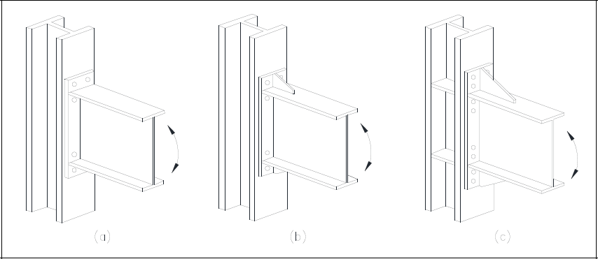
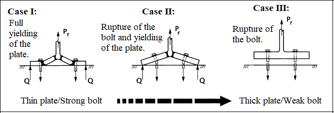
It consists of 3 different types.
-
The factors determining the behavior of the connections are beam cross-section reaching to yield under bending, end plate reaching to yield under bending, yielding of column panel zone, failure of bolts under tension, and rupture bolts under shear.
-
The controls listed above are applied automatically, and detailed explanations and references with parameters used in the computation are given in the report.
-
The YDKT method must be selected to report these connections used in the design of moment-resisting frame elements carrying earthquake loads together with TBDY 2018 and ÇYTHE 2018.
-
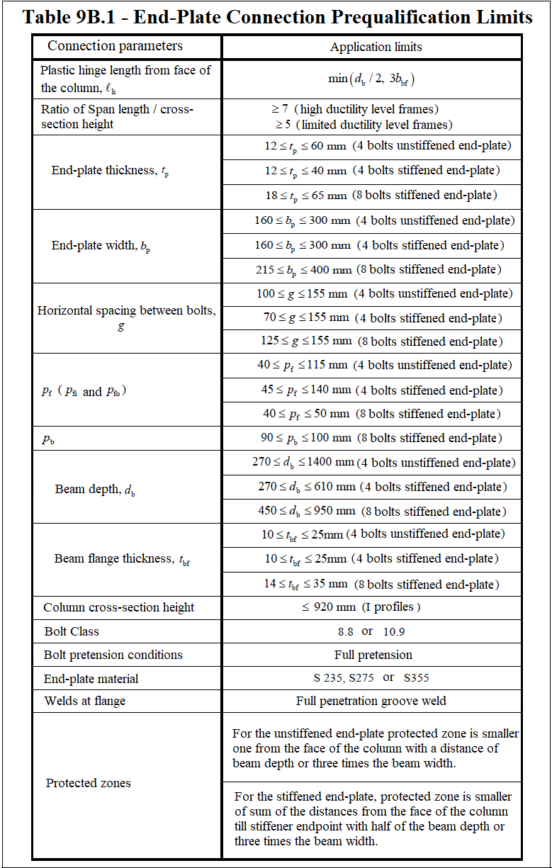
Some conditions must be met to be used in 3 types of moment-resisting frames with high or limited ductility levels. These conditions are given in TBDY 2018 Table 9B.1 according to the ductility level. ideCAD Structural Steel automatically checks and reports these conditions.
-
In the end plate connection, plastic hinges cause inelastic bending deformations in the beam and column panel zone. Therefore, strong connection, strong column and weak beam design are considered a basis. For this reason, the length of the plastic hinge and its distance from the column face is specifically checked from the table below:
Design Criteria for End Plate Connection
-
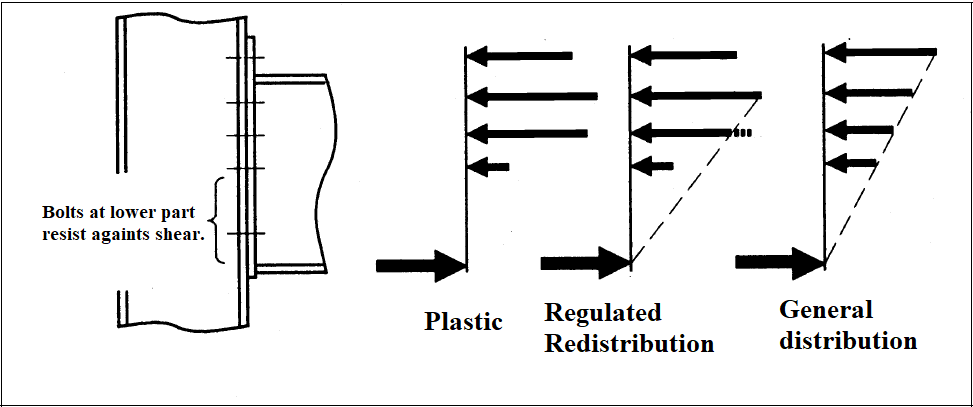
The strength of the end plate connection is determined by the assumption that the tensile force of the bolts on a part of the plate and compressive forces of the bolts on the other part of the plate is controlled by the bearing limit state.
-
If there is no axial load on the connection, the total tensile and compressive forces are equal and opposite in both parts which create force pair.
-
The row of bolts farthest from the compression part is considered as the region subject to the greatest tensile force, and the inverse triangular force distribution provides simplification on the calculation and a ductile connection is calculated on a parabolic distribution according to the plastic force distribution assumption.
-
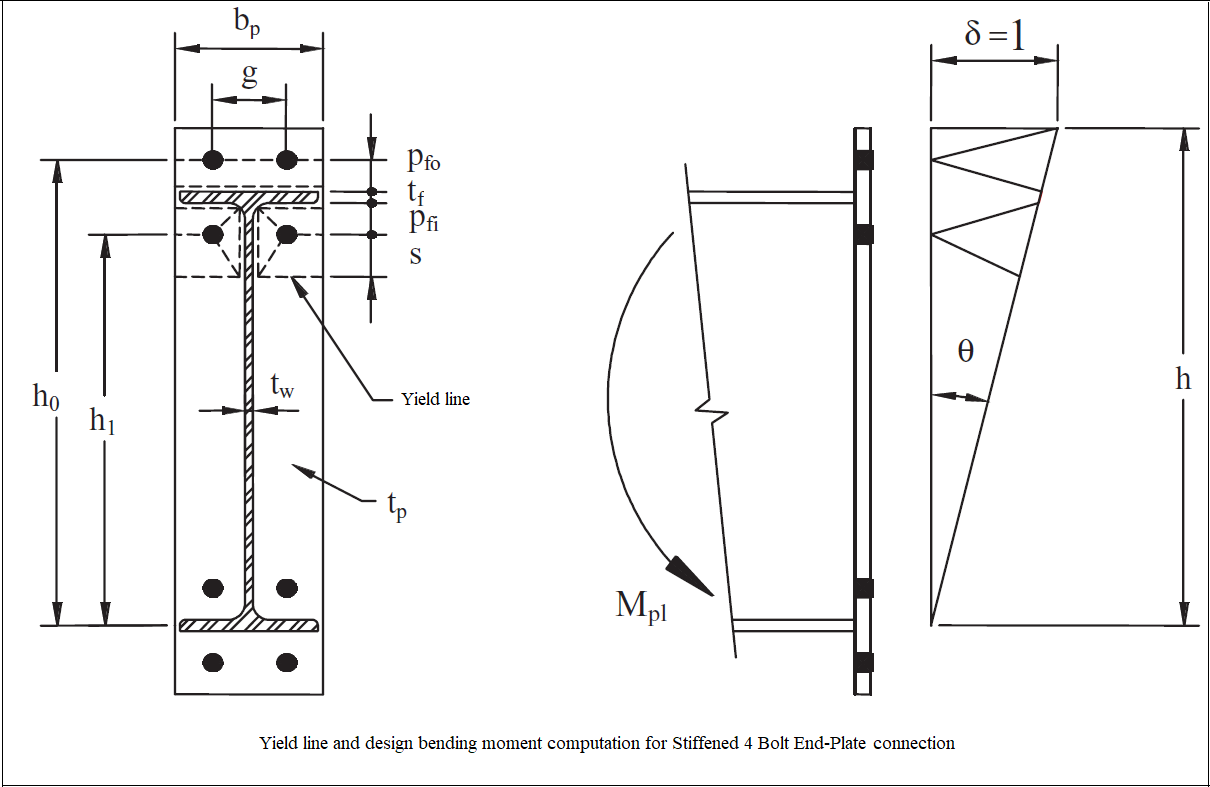
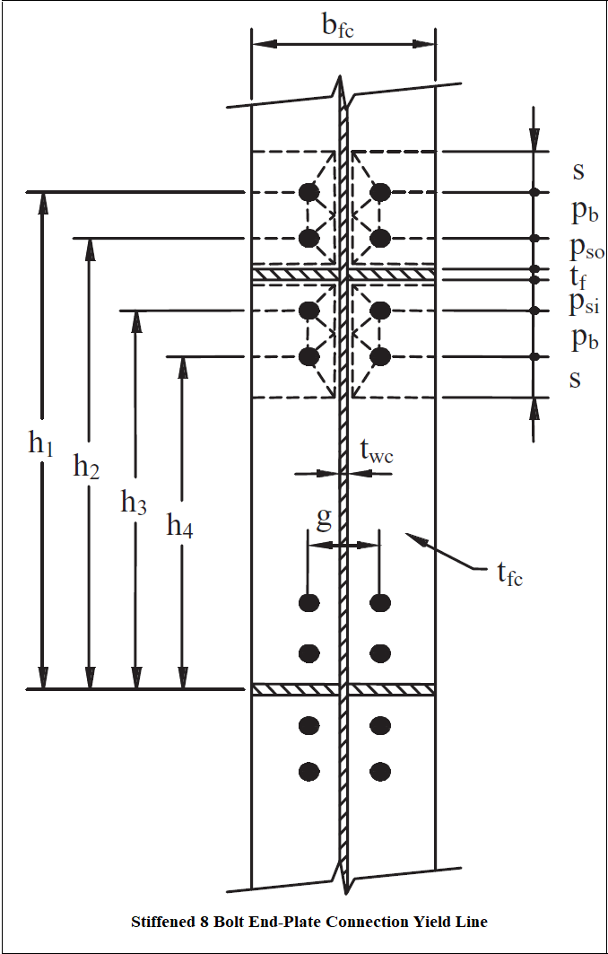
The bending strength of the end plate and the column flange is determined by the yield line method. The yield line method can be calculated by the energy or virtual work method.
-
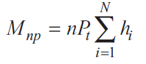
Strong column, strong connection and weak beam are used to compute the forces on the bolts and to find the required bolt strength. According to this assumption, the column panel zone and beam exhibit inelastic behaviour while the connection and column show elastic behaviour. For this reason, it is necessary to design the end plate as a thick plate. In thick plate behaviour, the force in the bolts is the static moment at the center of the compressive part.
-
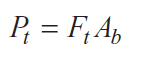
The equations used are as follows
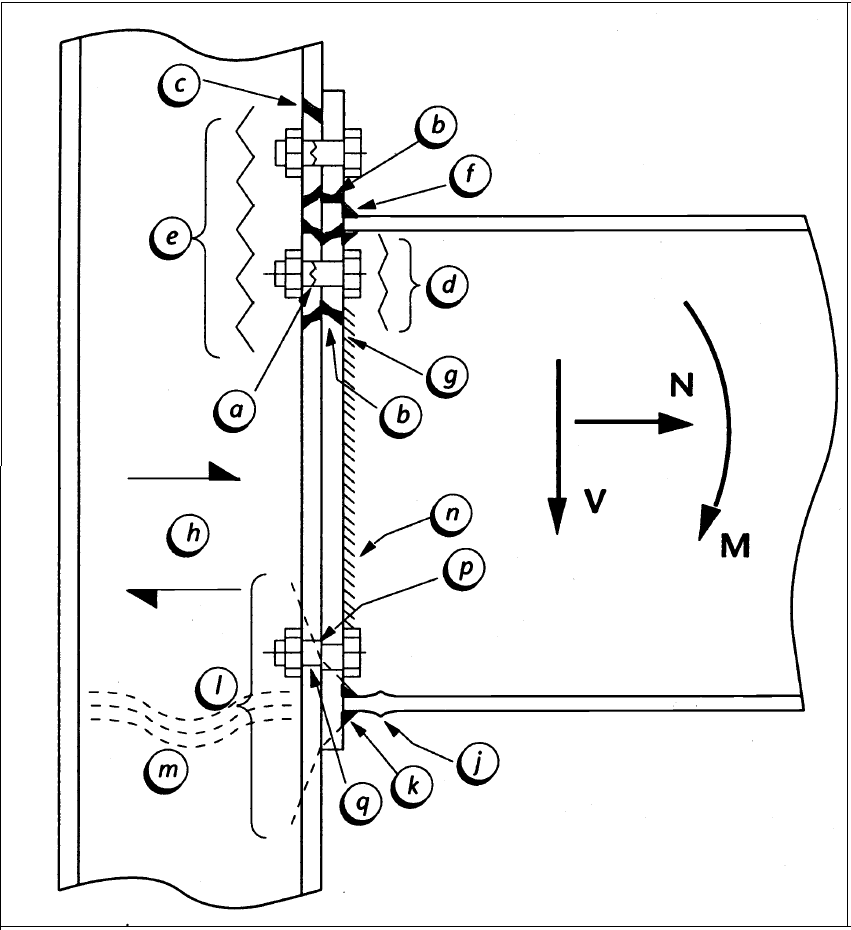
The Limit States to be Checked
|
Force |
Connection Element |
Reference |
|---|---|---|
|
Tension |
Bolt (Tension) |
a |
|
Tension |
Plate (Bending) |
b |
|
Tension |
Column Flange (Bending) |
c |
|
Tension |
Beam Web (Tension) |
d |
|
Tension |
Column Web (Tension) |
is |
|
Tension |
Flange - Plate Weld |
f |
|
Tension |
Web - Plate Weld |
g |
|
Horizontal Shear |
Column Web (Shear) |
h |
|
Compression |
Beam Flange (Compression) |
j |
|
Compression |
Beam Flange Weld |
k |
|
Compression |
Column Web |
l |
|
Vertical Shear |
Web - Plate Weld |
m |
|
Vertical Shear |
Bolt (Shear) |
n |
|
Vertical Shear |
Bolt Bearing |
p |
Download ideCAD for Connection Design
Next Topic