
In the performance analysis of existing structures (linear and non-linear), the interaction of reinforced concrete sections under the effect of biaxial bending and axial force is taken into account in the definition of plastic hinge, determination of unit deformation-plastic rotation demands and determination of cross-section plastic rotation-unit deformation limits. The information level coefficient and the existing material strengths are taken into account in the element capacities calculated for the performance analysis.
-
The interaction diagrams of the sections from the biaxial bending and axial force effect are automatically defined according to the defined information level, material strengths, section geometry and reinforcement placement.
The interaction of reinforced concrete sections under biaxial bending and axial force is taken into account in the definition of plastic joint, determination of unit deformation-plastic rotation demands and determination of plastic rotation-unit deformation limits within the scope of the evaluation of existing structures with the Assessment Based on Deformation Design (ŞGDT) approach .
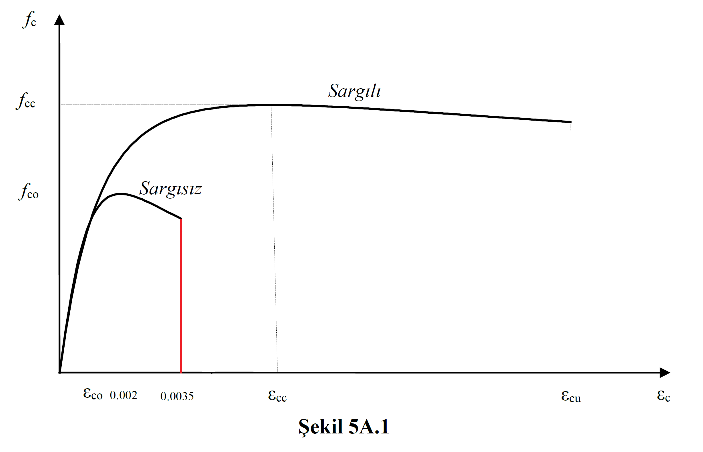
While creating the material model, the knowledge level coefficient and existing material strengths are taken into account (Information Level and Current Material Strength). The maximum compressive strain of concrete is taken into account as 0.0035. In this case TBDY Annex 5A is formed up to a strain value of 0.0035, and after this point, the concrete is considered to be crushed. Wrapped and uncoated concrete model is shown in Figure 5A.1In reinforced concrete elements, the winding effect is taken into account in the core region according to the transverse reinforcement situation. However, since the wrapping effect will increase the strain capacity, the strain limit of 0.0035 is only available in the unwrapped concrete model (shell region of the section).
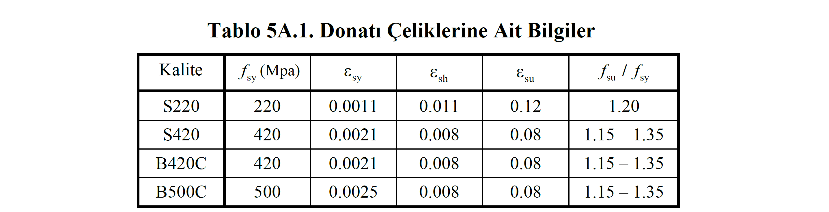
In the reinforcement model, the maximum unit deformation value is taken into consideration as specified in Table 5A.1 as defined in Annex 5A of TBDY Section .
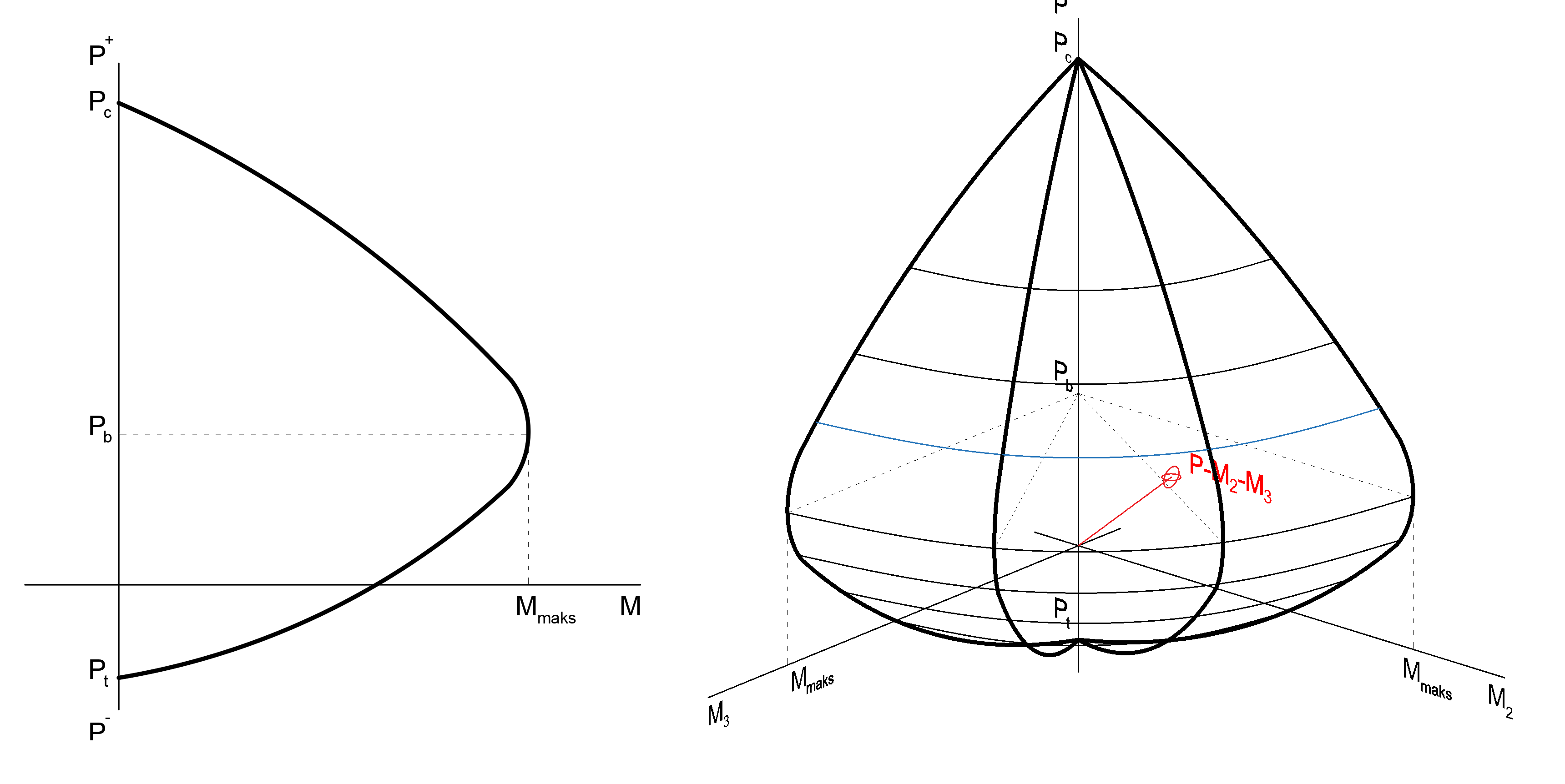
While creating the moment curvature relationship under the axial force and biaxial bending effect, the material models used above are taken into account. The interaction curve is created in three dimensions. The following picture shows the 3D interaction curve and the normal force bending moment graphs at a single angle of this curve.
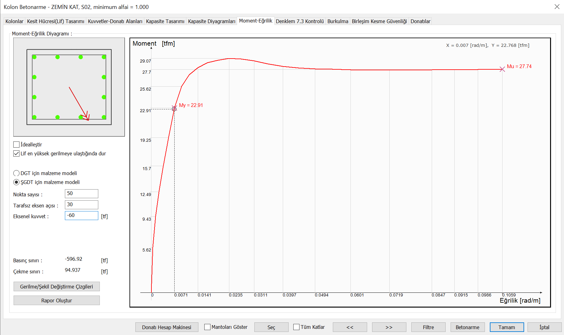
The picture below shows a moment curvature relationship drawn by considering confined and unwrapped concrete models of a sample column. Here, the neutral pivot angle represents biaxial bending and is the angle between the moment vectors of the cross section around the X and Y axis. The axial force value also represents the normal force on this element.
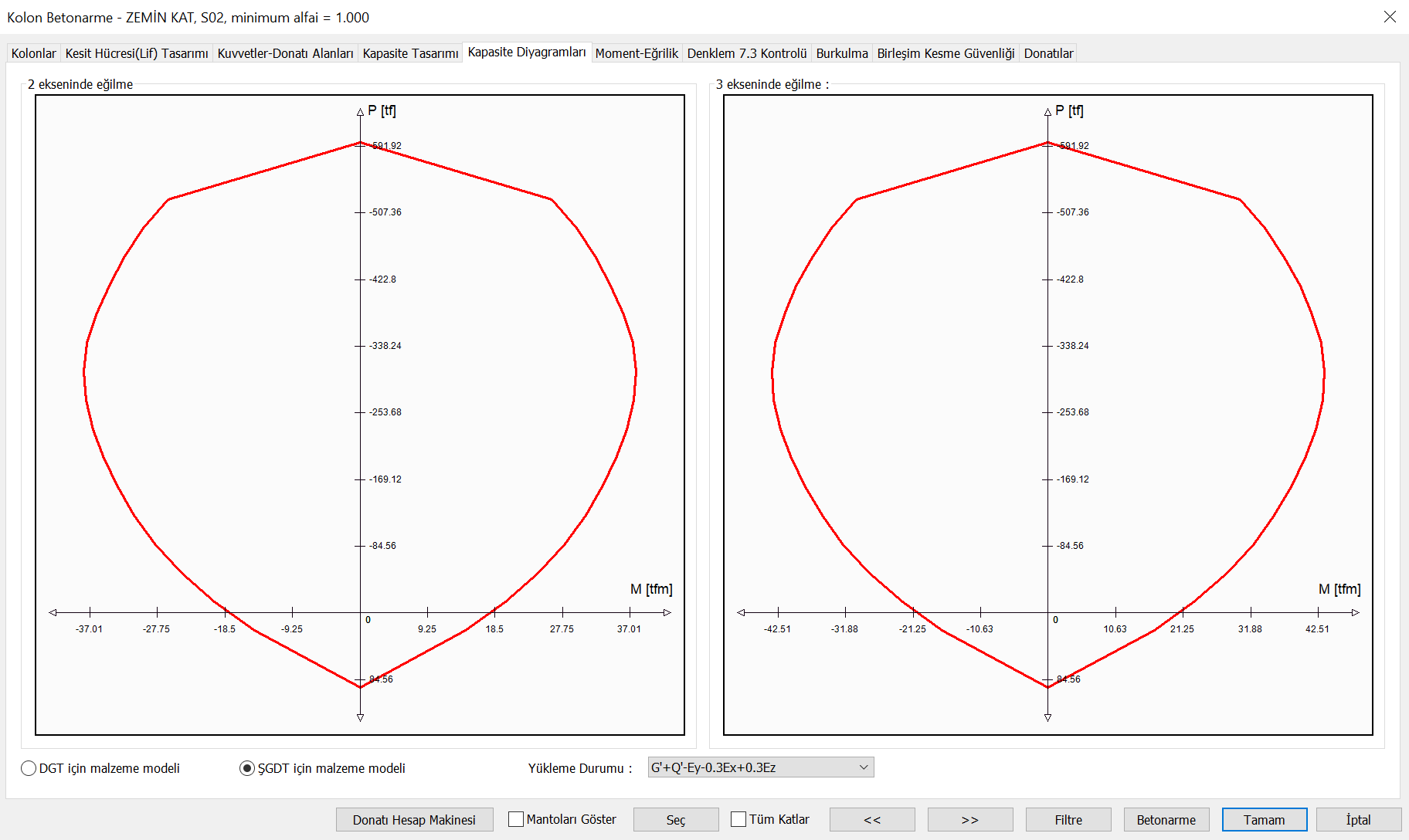
This process is done for each neutral axis angle of the element and for each axial force level. Thus, a three-dimensional interaction curve can be obtained. A moment-normal force relationship can be obtained at a single angle of these three-dimensional interaction curves. In the picture below, the relationship between bending moment and axial force around the (X) and (Y) axes is shown separately.
Next Topic