
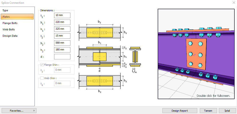
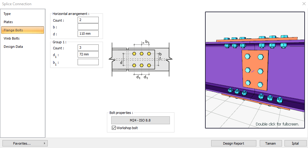
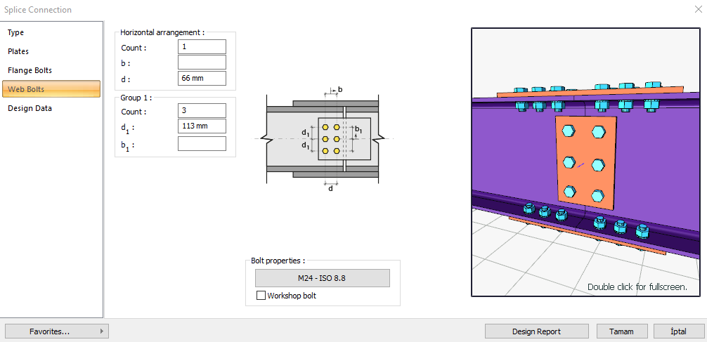
A splice connection design is a moment-transmitting connection formed by bolted or welded connecting plates of beam caps and bodies. It can be used as a beam attachment or column attachment. Bolt control, welding control, and plate control are made automatically according to the placement of the connection elements.
The splice connection design in ideCAD Structural is automatically made according to the Design, Calculation, and Construction Principles of Steel Structures AISC 360-16 regulations and the connection report is created.
Download ideCAD for Connection Design with AISC 360-16
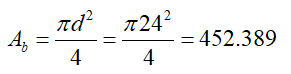
In the calculation of the splice connection, the distance between the header and the body bolts, the horizontal and vertical edge distance, and the welding control are made under the geometry control. In strength control, heading and body bolts slip, cap and body bolt hole crushing, beam cap and body bolt hole crushing, header plate tensile yield and tensile failure, head plate block slip, beam head block slip, head plate pressure leak, body plate block slip and weld control.
Connection Geometry
Geometry Checks
Bolt Spacing at Flange
|
|
ÇYTHYEDY 13.3.6 |
|
|
|
|
72 mm |
|
|
|
|
24 mm |
s =79.5 mm > smin = 3*24=72 mm |
√ |
Horizontal Edge Distance at Flange
|
|
ÇYTHYEDY 13.3.7 |
|
|
|
|
75 mm |
L eh ≥ 2d = 2 * 24 = 48 mm conformity check for application |
√ |
|
|
32 mm |
Minimum distance check according to Table 13.9 |
√ |
Vertical Edge Distance at Flange
|
|
ÇYTHYEDY 13.3.7 |
|
|
|
|
35 mm |
|
|
|
|
32 mm |
Minimum distance check according to Table 13.9 |
√ |
Bolt Spacing at Web
|
|
ÇYTHYEDY 13.3.6 |
|
|
|
|
112.5 mm |
|
|
|
|
32 mm |
s =112.5 mm > smin = 3*24=72 mm |
√ |
Horizontal Edge Distance at Web
|
|
ÇYTHYEDY 13.3.7 |
|
|
|
|
55 mm |
L eh ≥ 2d = 2 * 24 = 48 mm conformity check for application |
√ |
|
|
32 mm |
Minimum distance check according to Table 13.9 |
√ |
Vertical Edge Distance at Web
|
|
ÇYTHYEDY 13.3.7 |
|
|
|
|
50 mm |
L eh ≥ 2d = 2 * 24 = 48 mm conformity check for application |
√ |
|
|
32 mm |
Minimum distance check according to Table 13.9 |
√ |
Checks
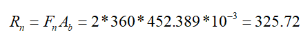
Bolt Shear at Flange
|
|
|
|
|
|
|
|
|
|
|
|
|
Required |
Available |
Ratio |
Control |
|---|---|---|---|
|
315,683 kN |
732.87 kN |
0.431 |
√ |
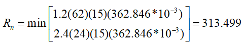
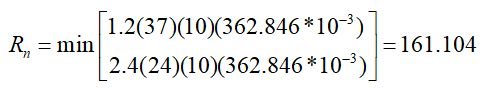
Bolt Bearing on Flange Plate
|
|
24+2=26 mm |
|
|
|
|
|
|
|
|
ÇYTHYEDY 13.3.13 Equation 13.14a and13.14b |
|
|
|
|
|
|
|
|
|
|
|
|
|
|

|
|
|
|
|
|
|
Required |
Available |
Ratio |
Control |
|---|---|---|---|
|
315,683 kN |
1371.558 kN |
0.230 |
√ |
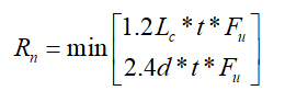
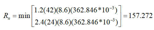
Bolt Bearing on Beam Flange
|
|
24+2=26 mm |
|
|
|
|
|
|
|
|
ÇYTHYEDY 13.3.13 Equation 13.14a and13.14b |
|
|
|
|
|
|
|
|
|
|
|
|
|
|

|
|
|
|
|
|
|
Required |
Available |
Ratio |
Control |
|---|---|---|---|
|
315,683 kN |
1234,402 kN |
0.256 |
√ |
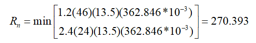
Flange Plate Shear Yield
|
|
|
|
|
|
235.359 N/mm2 |
|
|
|
|
ÇYTHYEDY 13.15 |
|
|
|
|
|
Required |
Available |
Ratio |
Control |
|---|---|---|---|
|
281.974 kN |
571.92 kN |
0.493 |
√ |
Flange Plate Tensile Rupture
|
|
|
|
|
|
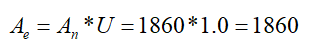
|
|
|
|
362.846 N/mm2 |
|
|
|
1.00 |
|
|
|
|
ÇYTHYEDY 13.16 |
|
|
|
|
|
Required |
Available |
Ratio |
Control |
|---|---|---|---|
|
281.974 kN |
506.17 kN |
0.557 |
√ |
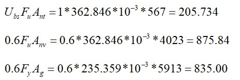
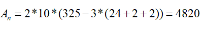
FlangFlange Plate Block Shear
|
|
|
|
|
|
|
|
|
|
|
|
|
|
235.359 N/mm2 |
|
|
|
362.846 N/mm2 |
|
|
|
one |
|
|
|
|
|
|
|
|
ÇYTHYEDY 13.19 |
|
|
|
|
|
Required |
Available |
Ratio |
Control |
|---|---|---|---|
|
281.974 kN |
867,285 kN |
0.325 |
√ |
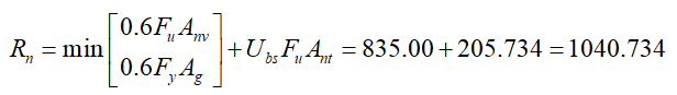
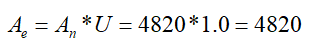
Flange Plate Block Shear
|
|
|
|
|
|
|
|
|
|
|
|
|
|
235.359 N/mm2 |
|
|
|
362.846 N/mm2 |
|
|
|
one |
|
|
|
|
|
|
|
|
ÇYTHYEDY 13.19 |
|
|
|
|
|
Required |
Available |
Ratio |
Control |
|---|---|---|---|
|
281.974 kN |
780.55 kN |
0.361 |
√ |
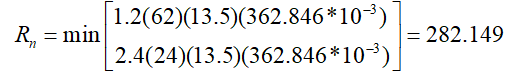
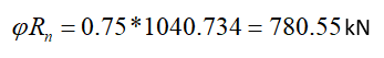
Beam Flange Block Shear
|
TO |
0.65 |
|
|
L |
150 mm |
|
|
r |
4.33 mm |
|
|
|
22.52 |
|
|
|
235.359 N/mm2 |
|
|
|
|
|
|
|
|
ÇYTHYEDY 13.19 |
|
|
|
|
|
Required |
Available |
Ratio |
Control |
|---|---|---|---|
|
315,683 kN |
571.92 kN |
0.552 |
√ |
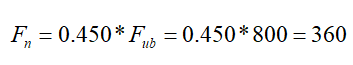
Bolt Shear at Web
|
|
|
|
Fn |
|
|
|
|
|
|
|
|
Required |
Available |
Ratio |
Control |
|---|---|---|---|
|
0.458 kN |
244.29 kN |
0.002 |
√ |
Bolt Bearing on Web Plate
|
|
24+2=26 mm |
|
|
|
|
|
|
|
|
ÇYTHYEDY 13.3.13 Equation 13.14a and13.14b |
|
|
|
|
|
|

|
|
|
|
|
|
|
Required |
Available |
Ratio |
Control |
|---|---|---|---|
|
0.458 kN |
241.656 kN |
0.002 |
√ |
Bolt Bearing on Beam Web
|
|
24+2=26 mm |
|
|
|
|
|
|
|
|
ÇYTHYEDY 13.3.13 Equation 13.14a and13.14b |
|
|
|
|
|
|
|
|
|
|
|
|
|
Required |
Available |
Ratio |
Control |
|---|---|---|---|
|
0.458 kN |
117.954 kN |
0.004 |
√ |
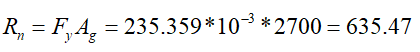
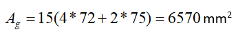
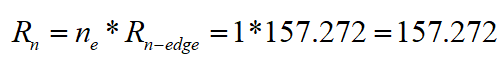
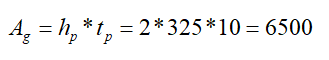
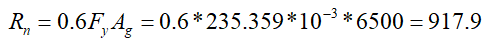
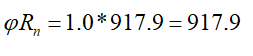
Web Plate Shear Yield
|
A g |
|
|
|
|
235.359 N/mm2 |
|
|
|
|
ÇYTHYEDY 13.17 |
|
|
|
|
|
Required |
Available |
Ratio |
Control |
|---|---|---|---|
|
1,108 kN |
917.9 kN |
0.001 |
√ |
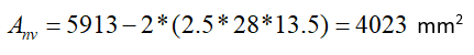
Web Plate Shear Rupture
|
A nv |
|
|
|
|
|
|
|
|
362.846 N/mm2 |
|
|
|
|
ÇYTHYEDY 13.17 |
|
|
|
|
|
Required |
Available |
Ratio |
Control |
|---|---|---|---|
|
1,108 kN |
787,013 kN |
0.001 |
√ |
Beam Shear Rupture
|
|
|
|
|
|
|
|
|
|
362.846 N/mm2 |
|
|
|

|
ÇYTHYEDY 13.17 |
|
|
|
|
|
Required |
Available |
Ratio |
Control |
|---|---|---|---|
|
1,108 kN |
443,732 kN |
0.002 |
√ |
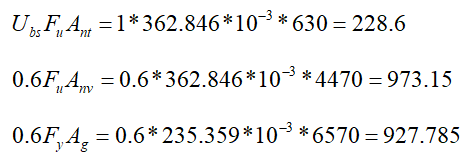
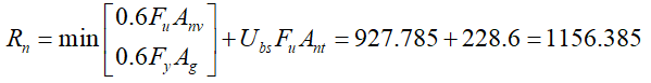
Web Plate Block Shear
|
|
|
|
|
|
|
|
|
|
|
|
|
|
235.359 N/mm2 |
|
|
|
362.846 N/mm2 |
|
|
|
one |
|
|
|
|
|
|
|
|
ÇYTHYEDY 13.19 |
|
|
|
|
|
Required |
Available |
Ratio |
Control |
|---|---|---|---|
|
1,108 kN |
805,664 kN |
0.001 |
√ |
Download ideCAD for Connection Design
Next Topic
Related Topics