
Symbols
A t = Equivalent area used in the empirical natural vibration period calculation [m2]
A wj = Body cross-sectional area of the jth wall [m2]
C t = Coefficient used in the empirical natural vibration period
D bi = Additional eccentricity amplification coefficient at the i'th floor
d fi (X) = (X) displacement consisting of the fictitious load imposed on the i'th floor in the calculation of the dominant natural vibration period of the building in the earthquake direction [m]
F fi (X) =(X) In the calculation of the dominant natural vibration period of the building in the direction of the earthquake, the fictitious load on the i'th floor [kN]
F iE (X) = (X) the equivalent earthquake load acting on the center of the i'th storey mass in the earthquake direction [kN]
f jE (S ) = Equivalent earthquake load acting on jth finite element node [kN]
g = Gravitational acceleration [m / s2]
H N = Total height of the upper part of the building above the basements [m]
H w = Curtain height [m]
h i = Height of the i'th floor [m]
I = Building Importance Factor
lwj = Length ofwall inplan [m]
N = Total number of floors in the upper section above the basement floors of the building
S aR (T) = Reduced design spectral acceleration [g]
S DS = Short period design spectral acceleration coefficient [dimensionless]
T = Natural vibration period [s]
T pA = Dominant natural vibration period calculated empirically [s]
T p (X) = (X) dominant natural vibration period of the building in the earthquake direction [s]
∆F NE (X) =(X) additional equivalent earthquake load acting on the Nth storey (top) of the building in the earthquake direction [kN]
η bi = torsional irregularity coefficient at i'th storey
Equivalent Earthquake Load Method will be applied separately for earthquakes affecting the building in vertical (X) and (Y) earthquake directions. The following equations (X) are given for the earthquake direction. In buildings with and without basement, 3.3.1 will be used for the definition of building base and building height .
4.7.1. Determination of Total Equivalent Earthquake Load
4.7.1.1 - In the (X) earthquake direction considered, the total equivalent earthquake load ( base shear force ) acting on the entire building , V tE (X) , Eq. It will be determined by (4.19) .
Wherein S ar ( T p (X) ), considering the received (X) earthquake direction 4.7.3 'to the natural vibration period judges the calculated building by T p (X) taking into account Eq. (4.8) from the calculated reduced design spectral acceleration ' shows ni. S DS is the design spectral acceleration coefficient defined in 2.3.2.2 for a short period .
4.7.1.2 - Eq. (4.19) at the m t building Eq. (4.20) and corresponds to the total mass calculated:
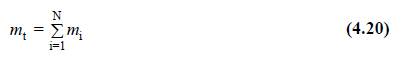
Where m i is the total mass of the i th floor slab.
4.7.2. Determination of Equivalent Earthquake Loads on Floors
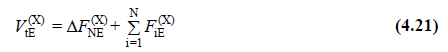
4.7.2.1 - The total equivalent earthquake load calculated with Equation (4.19 ) is expressed in Equation (4.21) as the sum of equivalent earthquake loads acting on the building floors :
4.7.2.2 - Construction N -th times (top) effect addition the lateral force Δ F NE (X) 'The value of Eq. (4.22) will be determined by.
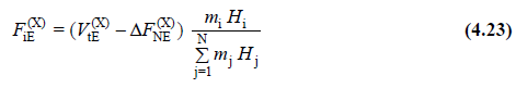
4.7.2.3 - total equivalent seismic load Δ F NE (X) other than the remaining portion of N 'including th floor, building floors to Eq. (4.23) will be dealt with.
4.7.2.4 - In case floor slabs are modeled as rigid diaphragm according to 4.5.6.4 , the equivalent earthquake load F iE (X) calculated by Equation (4.23) will be impacted in the earthquake direction taken into account on the main node point on the i'th floor .
4.7.2.5 - The floors 4.5.6.2 according plate ( membrane ) in the case of modeling by finite elements, the i-th layer in the jth point of the lateral force acting on the node Eq. (4.24) will be calculated by:
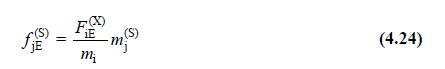
Here m ( j S) is the singular mass of the jth joint defined by Equation (4.16) .
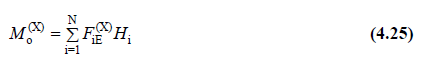
4.7.2.6 - The total overturning moment occurring at the base of the building from earthquake loads is calculated with Equation (4.25) :
4.7.3. Determination of the Building's Dominant Natural Vibration Period
4.7.3.1 - lateral force method 'in all buildings to the application of Eq. (4.19) , located in and considering the received (X) earthquake direction building dominant fundamental period expressing T p (X) , a more accurate calculation is performed, Eq It will be calculated by . (4.26) .
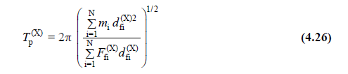
Here, F fi (X) , which shows the fictitious load acting on the i'th floor , will be obtained by substituting any value ( for example 100 ) instead of ( V tE (X) - ∆ F NE (X) ) in Equation (4.23) .
4.7.3.2 - The maximum value of the dominant natural vibration period T p (X) of the building calculated with Equation (4.26) to be taken into account in the earthquake calculation shall not be more than 1.4 times the period T pA given in 4.7.3.4 .
4.7.3.3 - DTS = 1, 1A, 2, 2A and IMS ≥ are 6 buildings and DTS = 3, 3a, 4a, the natural vibration period prevails in all buildings 4, 4.7.3.1 from the without calculating the direct 4.7.3.4 'in The given empirical T pA can be taken as the period ( T p (X) ≅ T pA ).
4.7.3.4 - Empirical dominant natural vibration period will be calculated with Equation (4.27) :
(a) delivery system only in buildings with reinforced concrete frame C t = 0.1, or from steel braced frame in buildings with steel frame C t = 0.08, all other buildings C t = will be 0.07.
(b) In buildings where all earthquake effects are covered by reinforced concrete walls, the C t coefficient will be calculated by Equation (4.28a):
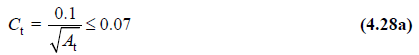
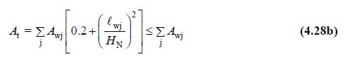
The equivalent area of A t in this relation is given in Equation (4.28b) :
4.7.4. Torsion Calculation in Equivalent Earthquake Load Method
Any i'th storey floor Table 3.6 at defined A1 event type and are irregularities, 1.2 <η b is with ≤ 2.0 is condition, 4.5.10.2 according exerted on the floor ± 5% additional eccentricity both earthquake to the direction of Eq. It will be enlarged by multiplying the D bi coefficient given in (4.29) .
4.7.5. Calculation of Basement Buildings Using Equivalent Earthquake Load Method
According to the definition given in 3.3.1 , in buildings with basements surrounded by rigid walls, the upper part of the building and the lower part with basement will be modeled together as a single structural system . One of the following two methods can be used in the earthquake calculation of such buildings:
(a) The calculation method described in 4.3.6.1 ,
(b) Calculation method with two load cases described in 4.7.5.1 , 4.7.5.2 and 4.7.5.3
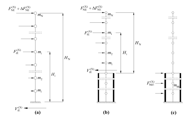
4.7.5.1 - In buildings with basements , the lower section (basement floors), which is relatively rigid in terms of horizontal rigidity with the upper section , have very different properties in terms of dynamic behavior and strength. In the two-load-state calculation approach , which can be applied for linear earthquake calculation with modal calculation methods of such buildings , the upper part of the building and the lower part with basement are modeled together as a single carrier system, but the reason for the vibrations of the upper part and the lower part in very distant modes. Earthquake calculation is done separately in two loading cases with:
4.7.5.2 - In case of initial loading, equivalent earthquake loads calculated according to 4.7.2.3 or 4.7.2.5 in the common single carrier system model are affected only on the upper section ( Figure 4.2b ). To the upper portion of accounts table (4.1) from the selected R top and the D top coefficients and the earthquake direction T p (X) according to the characteristic periods in Eq. (4.1) from the calculated seismic load reduction factor
( R a top ) will be used. As a result of the calculations made for a first load condition, and the upper portion from both the bottom portion from the reduced internal forces are obtained.
4.7.5.3 - case of the second installation still common single carrier system model, only the lower portion wherein the mass of basements, Eq. (4.8) from T = 0 placing the resulting reduced spectral acceleration S R (0) by multiplying the effects of these layers being equivalent earthquake loads are calculated ( Figure 4.2c ). In the calculation, the earthquake load reduction coefficient ( R a ) sub = D sub = 1.5 calculated from Equation (4.1 ) for the subsection (basement) will be used. As a result of the calculation made for the second loading situation,Reduced internal forces in the lower section are achieved.
4.7.5.4 - Internal forces essential to the design in buildings with basements are defined in 4.10.1 .