
How does ideCAD control the reentrant corner irregularity, according to ASCE 7-16?
-
The reentrant corner irregularity condition is determined by the user.
-
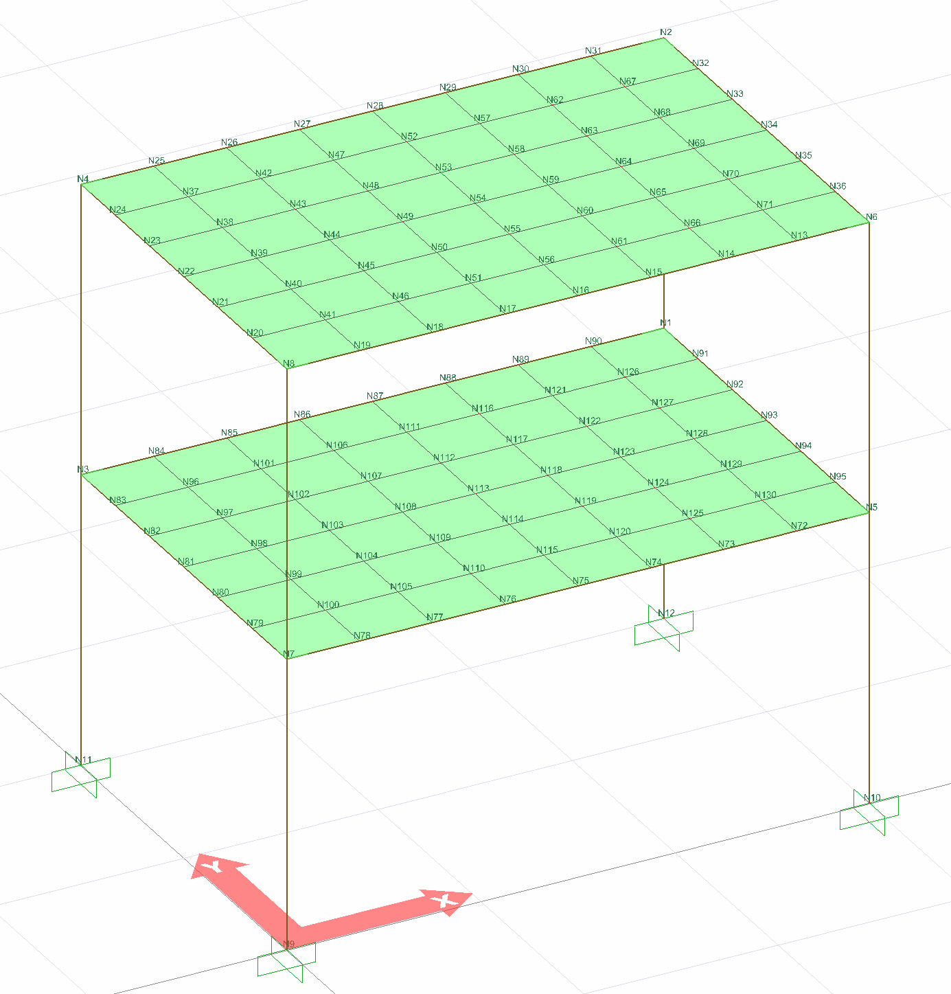
In buildings with Reentrant Corner type irregularities, story slabs are automatically modeled with two-dimensional plate (membrane) or shell finite elements to show that they can safely transfer earthquake forces between vertical bearing system elements in their own planes.
Reentrant Corner type irregularity situation occurs when both the dimensions of the reentrant parts of the building story plan in perpendicular directions to each other are greater than 15 % of the total length in the same direction as indicated in ASCE 7-16 Table 12.3-1.
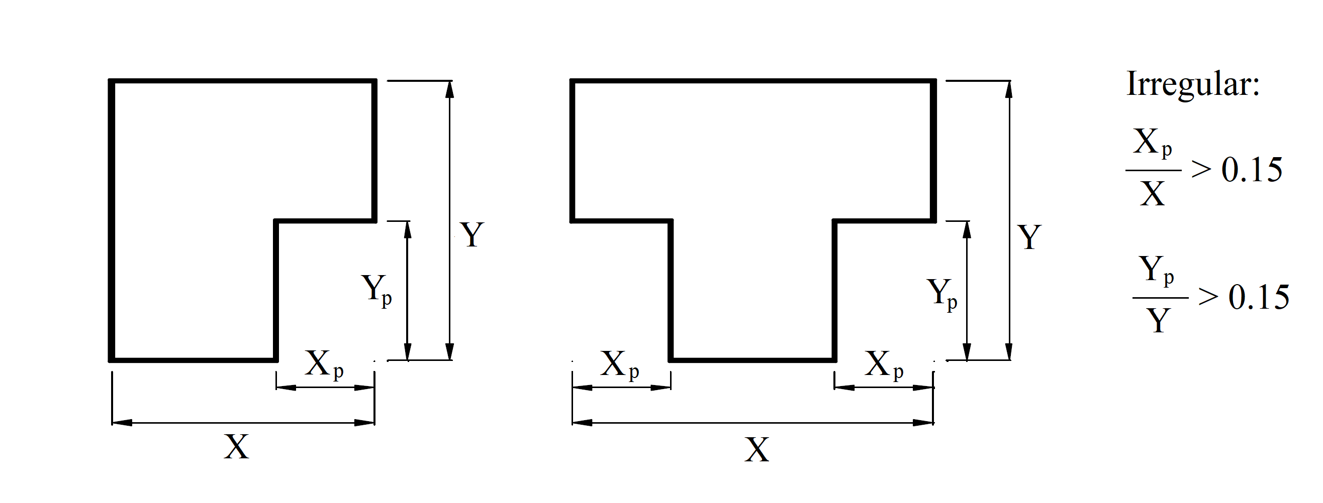
In the above figure, if X is the story plan length in the x direction, Xp is the length of the offset section in this direction. Similarly, if Y is the length of the story plan in the y direction, Yp is the length of the offset section in this direction.
-
Xp > X
-
YP > Y
Reentrant Corner type irregularity occurs in the building if the conditions occur simultaneously.
Buildings with reentrant corner-type irregularities are modeled with two-dimensional finite elements. The following picture shows the analysis model of an example whose slabs are modeled with two-dimensional finite elements (shell).
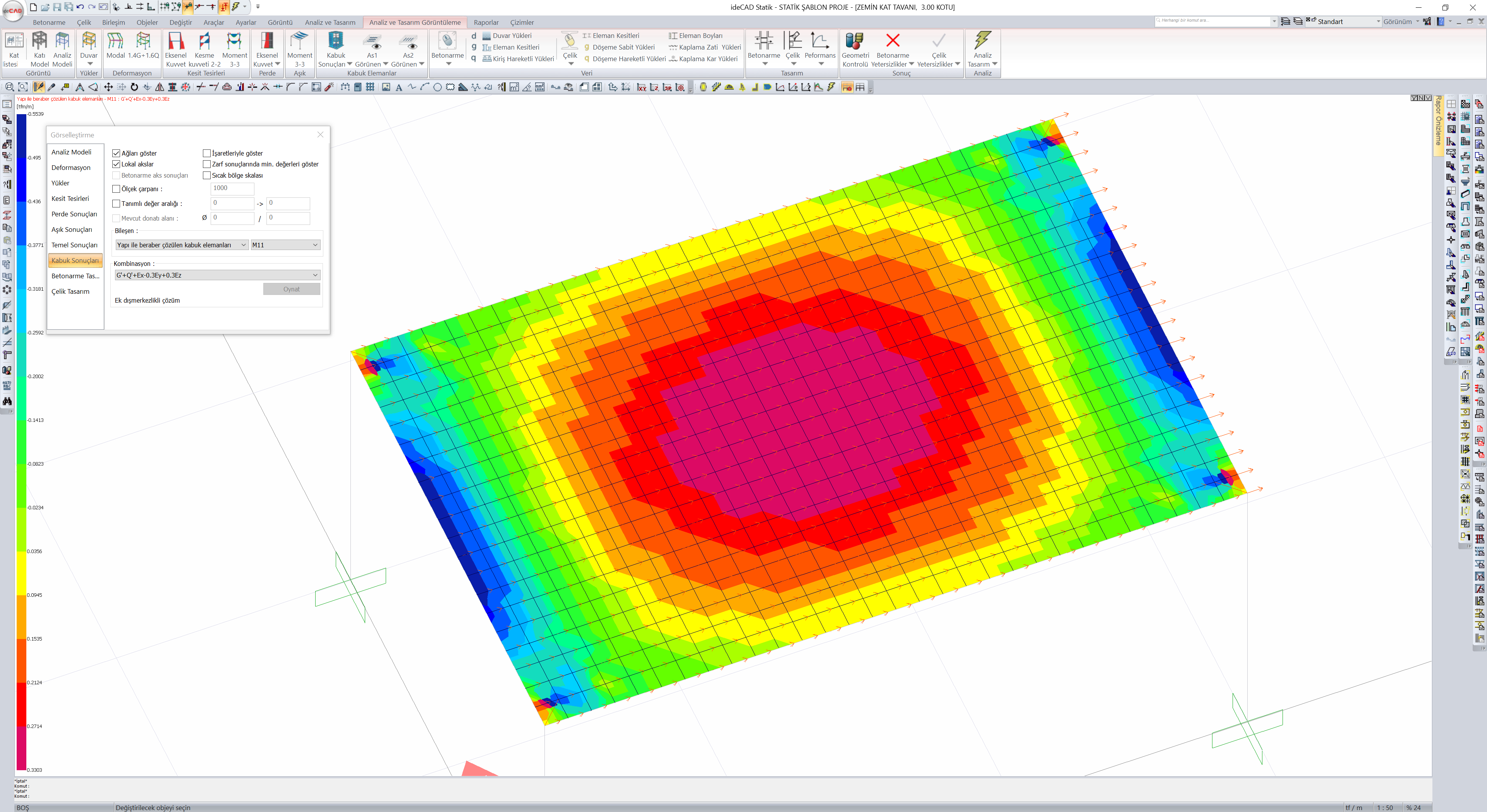
As a result of a three-dimensional analysis of shell finite elements (slabs, shearwalls, and polygonal walls), they generate stresses and forces per unit length. The directions of these stresses and forces per unit length are determined according to the local axes of the shell finite element.
Shell finite element forces are obtained as a result of stresses formed by finite shell elements in three-dimensional analysis.
-
M11, M22: Bending moments per unit length (tfm / m or kNm / m) formed around axes 1 and 2. They are also called out-of-plane bending moments.
-
M12: Means unit length planar torsion moment (tfm / m or kNm / m). It is also called the in-plane torsion moment.
-
V13, V23: Shell is the unit-length shear force (tf / m or kN / m) on the surface of the finite element and perpendicular to the plane of the finite element. It is also called the out-of-plane shear force.
-
F11, F22: Tensile and compressive forces per unit length (tf / m or kN / m) parallel to the plane of the acceptance finite element in the respective direction. It is also called in-plane pressure-pull forces.
-
F12: Unit length shear forces (tf / m or kN / m) parallel to the shell finite element plane. It is also called in-plane shear forces.
Shell finite element results can be viewed from the "Shell Results" tab in the Analysis Model.
Floor discontinuities cause accumulation in floor stresses caused by vertical loads and earthquake loads. The plan view and stress distribution of a system solved with semi-rigid diaphragm acceptance for reentrant corner type irregularity is shown in the picture below. As can be seen, in the structure containing reentrant corner-type irregularities, F11, which is the in-plane axial stress value, increased in certain regions.
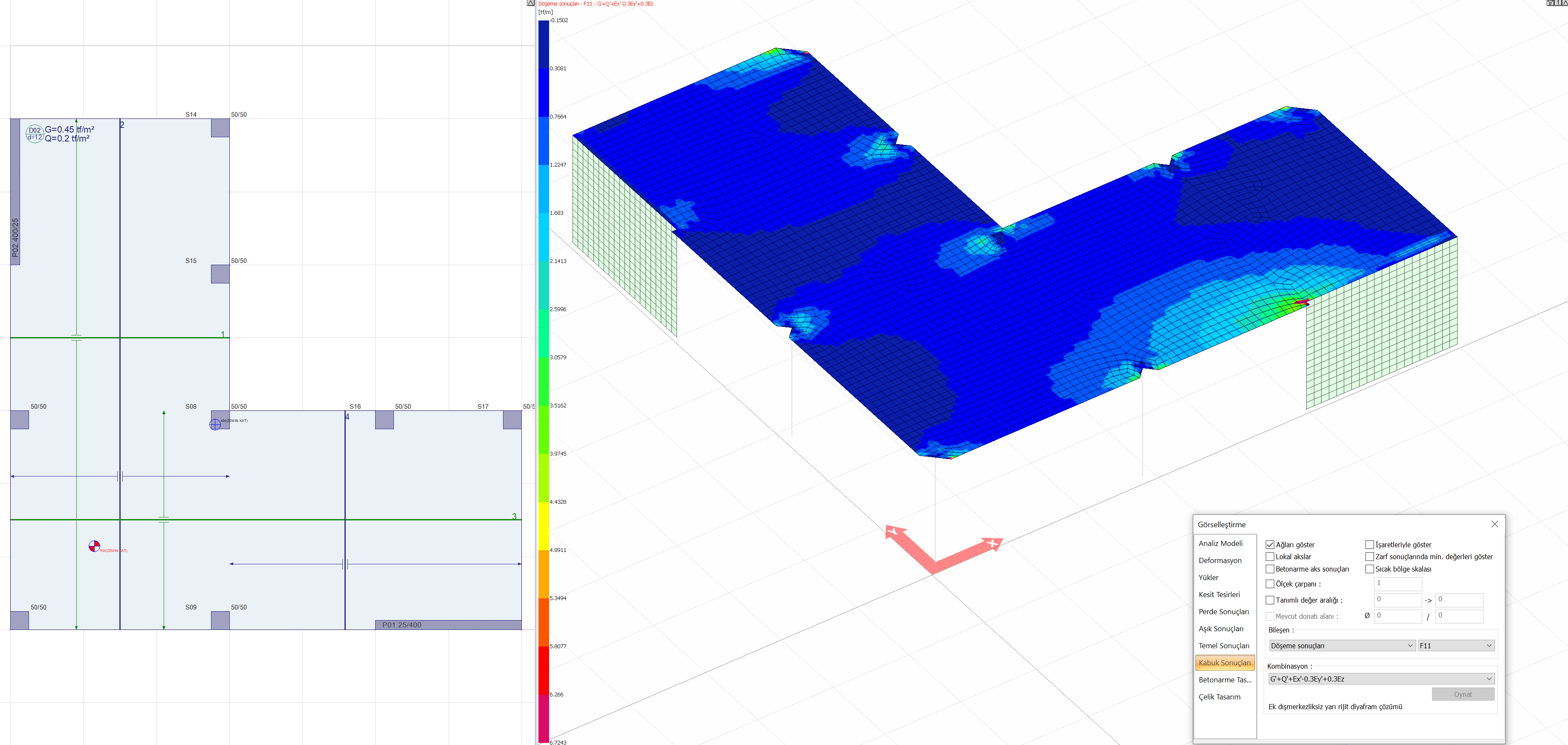
Reentrant Corner type irregularity occurs due to floor gaps. For this reason, slab in-plane deformations were neglected. Rigid diaphragm solution is not applied in this type of irregularity. In buildings with Reentrant Corner-type irregularities, a semi-rigid diaphragm solution should be made where the floors are modeled with finite shell elements.