
ICONS
D = Strength Excess Coefficient
f ck = Characteristic cylinder compressive strength of concrete
f yk = Characteristic yield strength of longitudinal reinforcement
H w = Total curtain height measured from the top of the foundation or the ground floor slab
H cr = Curtain critical height
l w = Curtain or tie-beam curtain part length in plan
( M p ) t = f ck at the base section of the curtain, f ykand the moment capacity calculated by considering the strength increase of the steel
( M d ) t = The moment calculated under the combined effect of the vertical loads and earthquake loads multiplied by the load coefficients at the base section of the wall
R = The load-bearing system behavior coefficient
V d = The vertical loads and earthquake loads multiplied by the load coefficients Shear force calculated under the joint effect
V e = Shear force based on transverse reinforcement calculation at column, beam, junction area and curtain
β v = Shear force dynamic magnification coefficient in curtain
For shear walls meeting the TBDY Article 7.6.6.3 - H w / l w > 2.0 condition, the design shear force to be taken as basis in calculating the transverse reinforcement in any section considered, V e shall be calculated by Equation (7.16).

The shear force dynamic magnification coefficient v = 1.5 in this equation shall be taken. However, β v = 1.0 can be taken in buildings where all of the earthquake load is carried by reinforced concrete walls . Where a more precise calculation is not made, (M p ) t ≤1.25 (M r ) t can be accepted here. The value obtained by increasing the vertical loads and the shear force calculated from the earthquake according to Section 4 by 1.2D (gapless walls) or 1.4D (bond beam walls) . If calculated by (7.16) is less than Ve, this shear force will be used instead of Ve. H w / l wDesign shear forces in all sections of walls with 2.0 shall be taken equal to the shear forces calculated according to Section 4 .
Design shear forces in all sections of walls with H w / l w ≤ 2.0 shall be taken equal to the shear forces calculated according to Section 4 .
TBDY Figure 7.12 (c) shows the shear force plot of the curtain design. The design shear force at the top of the curtain will be taken as half of the design shear force generated at the curtain base. H w / 3 'to be larger than the portion H w / 3 from the highest point of the screen by shear force at the half of the pitch base received shear force combined with a linear line design shear force will be created.
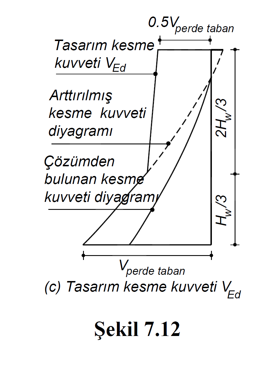
The shear forces in the graph shown in TBDY Figure 7.12 (c) are explained below.
"The shear force diagram found from the solution" is the shear force diagram calculated under the combined effect of vertical loads and earthquake loads.
The diagram shown with the "increased shear diagram" is the shear force diagram resulting from the increment mentioned in the TBDY Article 7.6.6.3 . In this shear diagram, Equation. The shear force and vertical loads calculated by (7.16) are compared with the shear force value obtained by increasing the shear force calculated from the earthquake according to Section 4 by 1.2D (gapless walls) or 1.4D (bond beam walls) and the smaller shear force is taken into account. taken.
The diagram shown with "Design shear force V Ed " is the same diagram as the "Increased shear diagram" in the region of H w / 3. H w / 3 In the region above the H w / 3 points in enhanced shear-shear force is taken as half the wall base at the highest point of the screen is the shear force generated in combination with a linear line.
Next Topic