
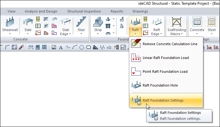
With the Raft Foundation Settings command, settings such as concrete raft foundation size, elevation, material selection, structural material can be accessed.
Location of the Raft Foundation Settings Dialog
The raft foundation that appears on the screen after running the raft foundation command is available in the auxiliary toolbar.
You can access it under the Concrete tab Foundation title in the ribbon menu .
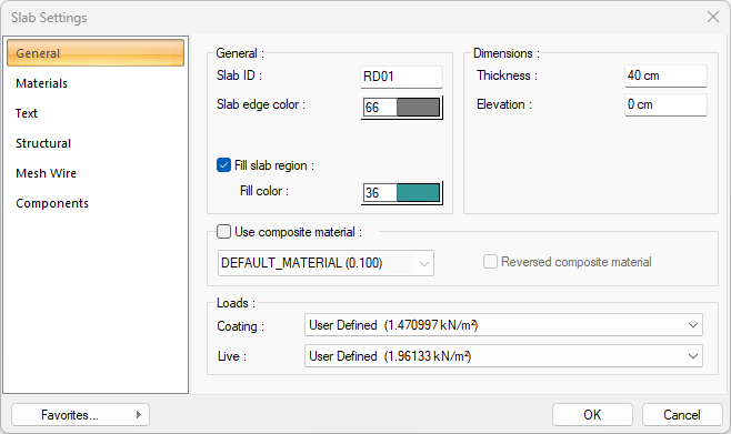
General Tab
|
Specifications |
|---|
|
Slab ID It is the name of the raft foundation. The number of raft foundation increases according to the order in which the raft foundation is drawn (RD01, RD02, RD03 etc.) If desired, the raft foundation names can be changed later with the Label Entities command. |
|
Slab edge color The color of the raft foundation edge lines is adjusted. Click on the color box with the left mouse button and the mouse cursor slides over the opened color palette. The button is released when the desired color is reached. The color box turns into the selected color. If the color box is clicked on the keyboard with the shift key, the pen thickness of the corresponding color can be adjusted. |
|
Fill slab region If the option is selected, the area within the raft foundation will be shown painted in the plan. |
|
Fill color The color in which the inside of the raft foundation will be painted is adjusted. Click on the color box with the left mouse button and slide the mouse cursor over the opened color palette. When the desired color is reached, the key is released. The color box turns into the selected color. If the color box is clicked with the shift key on the keyboard, the pen thickness of the relevant color can be adjusted. |
|
Thickness The raft foundation height is entered. The floor starts from the foundation ceiling and hangs down to the given height. If the foundation height is increased, the foundation becomes thicker downwards. |
|
Elevation The raft floor level is entered. When the elevation is zero, the raft floor top surface is level with the floor base. If a positive value is entered, the raft slab rises up from the floor floor, if a negative value is entered, it falls under the floor floor. |
|
Use composite material 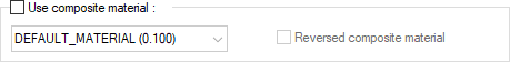
Composite materials allow the slab to be drawn in a different material view in cross-section. If checked, it allows the use of materials defined in the "Composite Material" editor. After the row is marked, one of the composite materials in the list below is selected with the left mouse button. Changes the appearance of the slab in section according to the selected composite material. |
|
Reversed composite material If marked, the materials used in raft foundation are reversed. When the section is taken, the top hatching in the site section area appears at the bottom and the bottom hatch at the top. |
|
Coating 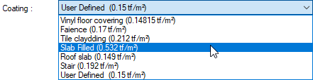
The appropriate value for the coating load is selected from the list. The values listed in the list are the values defined in the slab load library and are prepared only for the foundation weight. The reinforced concrete weight of the raft foundation will be added automatically during the analysis. If you want to use another value instead of using one value in the list, select "user-defined" from the list and enter a value. |
|
Live 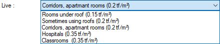
Select the appropriate value for live load from the list. The values that appear in the list are the values defined in the foundation load library. If you are going to use another value ifoundationnstead of using one value in the list, select "user defined" from the list and enter a value. |
Materials Tab
|
Specifications |
|---|
|
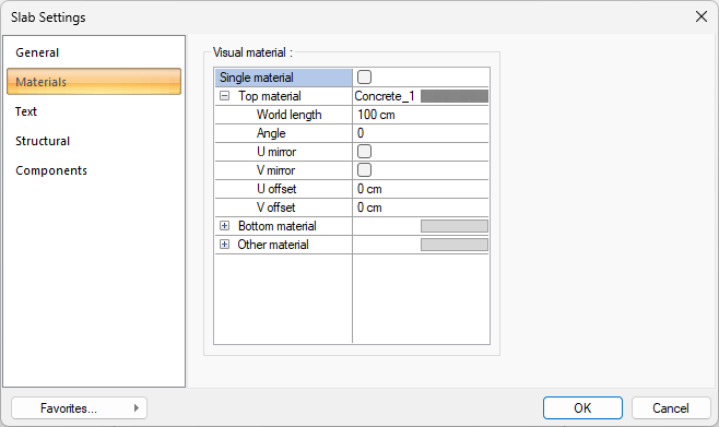
Visual material 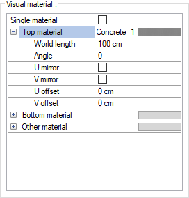
The material to be used on the top, bottom and other surfaces of the raft foundation is selected from the list. Surfaces are covered with the selected material and displayed as such in renderings. Texture length is entered into the world length. For example; If 1 is entered, the selected material texture is taken as 1 meter and covered on the relevant walls. In the angle, the angle of the texture is entered. Touch the U and V offset. The motion value in the x and y plane is entered. With U and V mirroring, the texture is symmetrical with respect to the y and x planes. By selecting the single material option, the material selected in "Top material" is used on all surfaces of the slab foundation. |
Text Tab
|
Specifications |
|---|
|
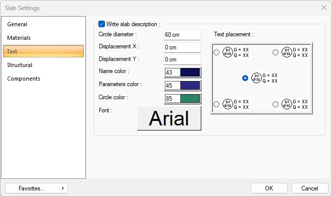
Write slab description If the raft foundation name, height and load information are desired to be written on the raft slab, it is marked. |
|
Circle diameter Give the raft foundation label circle diameter. |
|
Displacement X/Y Give the horizontal and vertical offsets according to the placed raft foundation circle. |
|
Name Color Raft foundation name color. To select a color, click and hold the left mouse button on the color box and drag it across the color palette that opens. Release it when you hover over the color you want. |
|
Parameters color The color of the cladding and live load and raft foundation height text defined on the raft foundation is adjusted. Click on the color box with the left mouse button and the mouse cursor slides over the opened color palette. The button is released when the desired color is reached. The color box turns into the selected color. If the color box is clicked on the keyboard with the shift key, the pen thickness of the corresponding color can be adjusted. |
|
Circle color The color of the circle that includes its height is adjusted with the name raft foundation. Click on the color box with the left mouse button and the mouse cursor slides over the opened color palette. The button is released when the desired color is reached. The color box turns into the selected color. If the color box is clicked on the keyboard with the shift key, the pen thickness of the corresponding color can be adjusted. |
|
Font The Font Settings dialog opens by clicking the Font button. The font is set in this dialog. |
|
Text placement 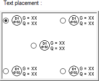
The location of the raft foundation text on the raft foundation is selected. |
Structural Tab
|
Specifications |
|---|
|
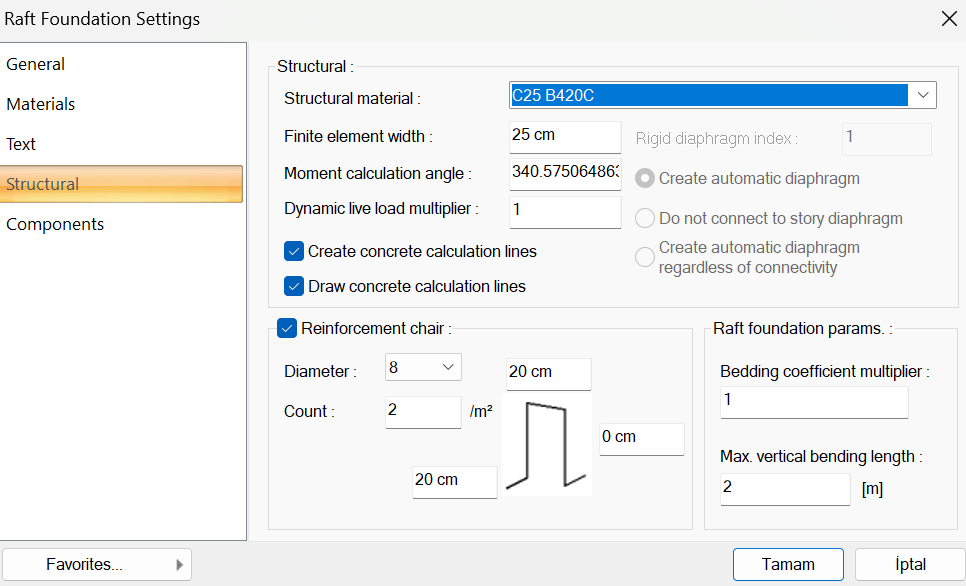
Structural material Select the structural material to be used in the element from the list. Structural material can be defined as a reinforced concrete element under Materials in Building Tree. |
|
Finite element width Enter the maximum finite element width to be taken as basis in the raft foundation calculation. The program makes the raft foundation analysis by dividing the foundation into trapezoidal finite elements. Finite element width is automatically adjusted according to the raft laying shape, provided that it does not exceed the value entered in this row. |
|
Moment calculation angle It is the parameter that determines the axis of the raft foundation moments in 3-dimensional view. The value entered here is the calculation angle according to the horizontal x axis. The moments of a foundation that are normally parallel to the global X axis are displayed in horizontal and vertical directions. By changing this parameter, moment calculation according to different axises can be seen in 3 dimensional view. However, as it is known, reinforced concrete calculation axis is defined in the program for slab reinforced concrete. Reinforced concrete accounts have nothing to do with this parameter. The program calculates reinforced concrete according to slab reinforced concrete calculation axises. |
|
Dynamic live load multiplier This box is irrelevant for the raft foundation settings. |
|
Create concrete calculation lines When the raft foundation is placed, this option can be selected in order for the reinforced concrete calculation axises to be defined in the foundation for foundation reinforced concrete automatically by the program. In this case, two horizontal and vertical reinforced concrete calculation axises are created in the middle of the foundation. If the option is not selected, the user can define the reinforced concrete calculation axises in any way and in number by using the "reinforced concrete calculation axis" command for the foundation reinforced concrete. |
|
Draw concrete calculation lines If it is wanted to show the reinforced concrete calculation axises showing the direction in which the raft foundation reinforced concrete will be made, it is marked. This representation is for informational purposes only and is not drawn in the formwork and / or reinforcement plans. |
|
Diameter The diameter of the trestle reinforcement is entered. |
|
Count The number of the stand reinforcement per square meter is entered. |
|
Reinforcement Chair 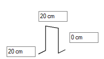
The dimensions of the reinforcement chair are entered. The height of the reinforcement chair is found by subtracting the foundation mat from the foundation height. The negative or positive value to be written on the height is added to the height value calculated by the program. Height of the reinforcement chair = foundation height - 2 * raft concrete cover thickness + entered value |
|
Bedding coefficient multiplier It gives the possibility to change the horizontal coefficient value that can be defined in the settings for the current raft foundation. The horizontal coefficient value is used by multiplying the entered ratio. With this possibility, the horizontal coefficient can be accepted at a different value for each raft area. |
|
Maximum vertical bending length It is the parameter that determines the miter length for the reinforcements made of miter. Normally, the miter raft thickness is the value found by subtracting the net concrete cover thickness from the bottom and top, but in cases where the raft thickness is large, the miter thickness is limited to the value entered in this line: Select the structural material to be used in the element from the list. Structural material can be defined as a reinforced concrete element under Materials in Building Tree. |
Components Tab
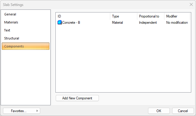
Add Building Components: Assigns the building materials defined for detailed building components metering to the object.
-
Click on the building components button.
-
The Component Selection dialog will open.
-
In this dialog, click on the folder related to the material from the list on the left. Click on the material you want to use.
-
Set the parameters on the right.
-
Click the OK button. The "Component Selection" dialog will be closed. A summary line of the material will appear in the Building Components tab. More than one material assignment can be made to an object.
The parameters available in the component selection dialog are:

In the usage section
No modification: The amount of material to be assigned for the object in question is marked when it is desired to be used in the size that was previously specified in the material definition.
Percentage: This line is marked when it is desired to be used with the percentage of the amount previously determined in the material definition, as much as the value entered in the "Value 1" line in the same dialog. For example, if the material quantity is 70, if the line “Value 1” says 40, it means the material amount will be used up to 40 * 70%.
Override: This line is marked so that the quantity entered in the “Value 1” line in the same dialog will be used instead of the quantity previously determined in the material definition.
Multiplier: This line is marked in order to use the value found at the end of the multiplication of the value entered in the "Value 1" line in the same dialog with the amount previously determined in the material definition.
Fraction: This line is marked so that the amount determined in the material definition before will be used as the fraction value created by the values entered in the "Value 1" and "Value 2" lines in the same dialog. "Value 1" is the denominator "Value 2" is the denominator.
Proportional to: It is determined to what scale-area, circumference, length etc.-, region-side area, top, edge etc.- the material will be proportioned to. The content of the proportional list box is automatically determined according to the object and the size of the material. For example, a different list will be created if an operation is made for the column, a different list will be created for the library, a different list for the volume, and a different list for the field.
The lines that appear in the Proportion list according to the raft foundation object and material size are as follows:
|
Raft Foundation |
||
|
Measure |
Listed |
Explanation |
|
Constant |
Independent |
The fixed measure used will be used exactly as the amount. |
|
Length |
Independent |
It means that the length measure found while defining the material will be used exactly as the length value. |
|
Perimeter |
It means that the length of the material will be found by multiplying the perimeter of the foundation with the length measure found while defining the material. |
|
|
Area |
Independent |
It means that the area measure found while defining the material will be used exactly as the amount. |
|
Top area |
The value to be found by multiplying the area measure found when defining the material with the area of the surface remaining on the slab means to be used as the material area. |
|
|
Bottom area |
The value to be found by multiplying the area measure found when defining the material and the area of the surface under the floor means to be used as the material area. |
|
|
Top and bottom area |
When the material is defined, the value found by multiplying the sum of the area measure found at the top and bottom of the foundation and the surface areas remaining at the top and bottom of the foundation means to be used as the material area. |
|
|
Volume |
Independent |
The volume measurement found when defining the material will be used exactly as the volume value. |
|
Volume |
It means that the volume measurement found when defining the material will be used by multiplying the foundation volume. |
|
|
Count |
Independent |
The number measure found while defining the material will be used exactly as the material number. |
|
Count |
The number measure found while defining the material will be used exactly as the material number. |
|
Next Topic