
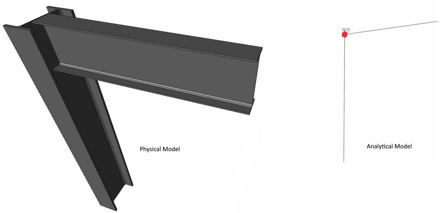
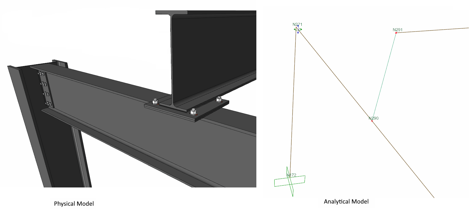
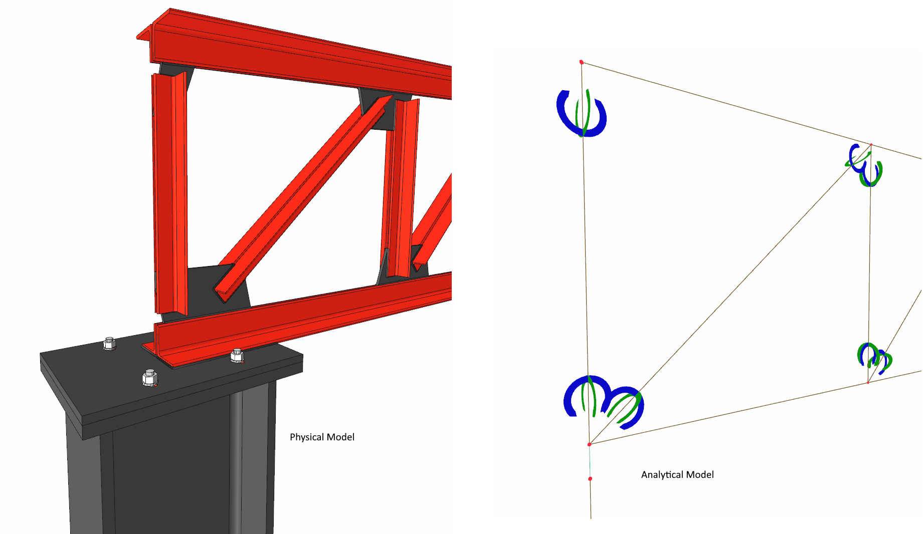
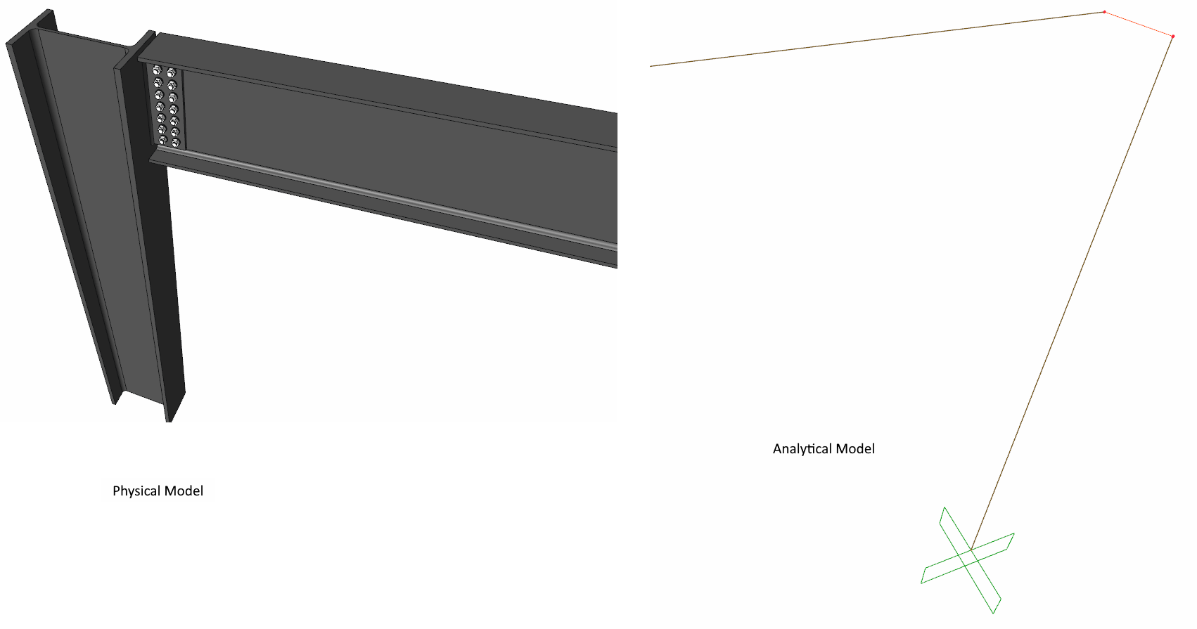
The physical model created at the interface during building modeling is converted into an analytical model according to the finite element method. In the analytical model, steel elements are modeled as a rod element according to the finite element method. Different connection types, namely boundary conditions, are created according to the offset and connection types used in this modeling. There are 4 types available as single connection with orange, green and blue links .
Single connection: If steel column and steel beam elements are modeled with middle offset, no link is formed in between. The only connection created, the node point, is represented in the analytical model with 6 degrees of freedom.
Green Link: It connects steel columns and beams as a rigid link in its own long axis direction. The translation values are the same, and the rotation values are different between the two joints where the link is defined.
Purlins included in the analysis are used in connections between trusses and beams placed on the column and the columns.
Blue Link: The degrees of freedom between the two joints where the link is located are equal. The same translation and rotation values are obtained. The main beam such as the secondary beam at the top, overhead connections and so on. used in geometries.
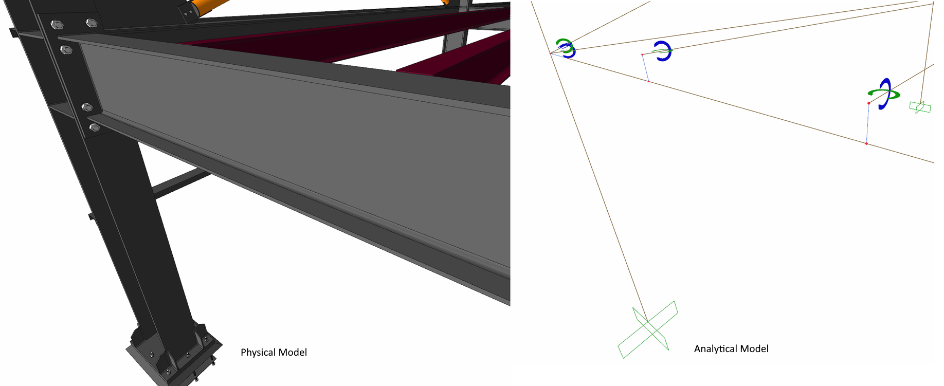
Orange link: Represents rigid behavior. It provides an infinitely rigid behavior between two nodes where it is defined. Steel column - steel beam connection points are formed by offsetting the steel beam.
Next Topic
Related Topics