
-
It is automatically controlled that all of the earthquake effects are met by bond beam (hollow) and / or non-void walls in reinforced concrete buildings or curtains with limited ductility level in structural systems containing only beamless floors.
-
In steel buildings, the use of central and / or eccentric braced or prevented braced frames or central braced frames with limited ductility level is under user control.
-
The calculation of such systems is done in two stages. In the first stage calculation, frame columns are taken automatically from the bottom and from the top. In the second stage calculation, the connections of these elements are modeled monolithically automatically. Internal forces in walls, columns, crosses and floors are automatically calculated as those obtained in two steps. Relative story offsets are automatically obtained from the second stage calculation.
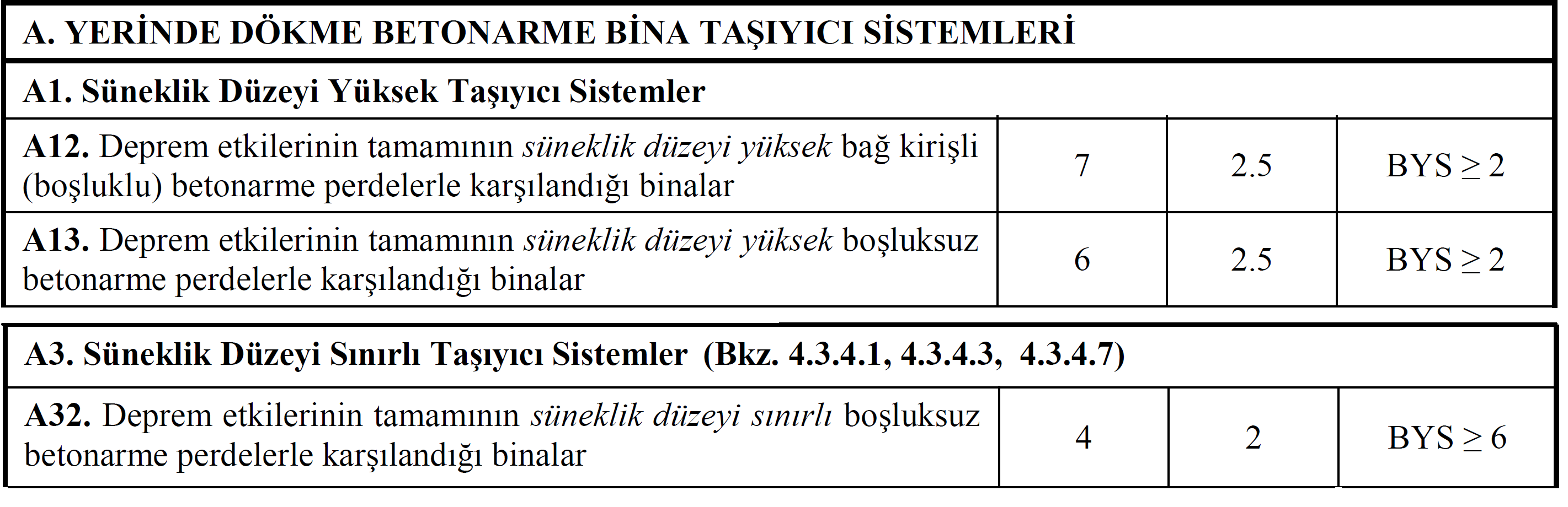
In reinforced concrete structural systems containing only beamless floors, all of the earthquake effects will be covered by walls with high ductility level and / or voids without or with limited ductility level . In this case, only the A12 , A13 and A32 load-bearing systems shown below can be used for cast-in-place reinforced concrete buildings with non-beam floors .
According to Article 4.3.4.4 of TBDY, the calculation of carrier systems containing beamless floors is made in two stages.
-
In the first stage calculation, frame columns are hinged from the bottom and from the top. In this case, all of the earthquake effects are covered by cavity or non-gap curtains.
-
In the second stage calculation, frame columns are modeled as monolithic.
Internal forces occurring in the structure such as curtain, column, slab, punching controls are calculated as the unfavorable of the results obtained in two stages.
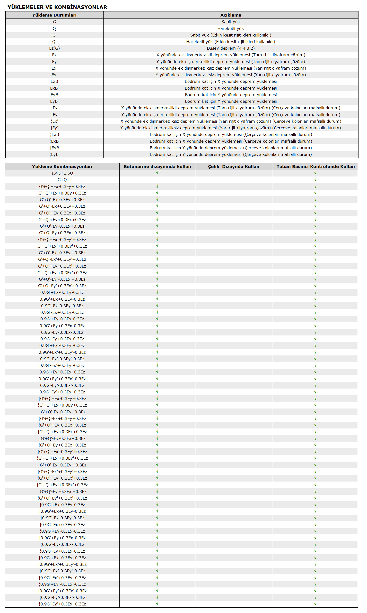
The report shown below shows the loading conditions and load combinations (combinations) of a reinforced concrete building with no rafters. In this table, loading cases such as Ex, Ey, Ex ', Ey' without any sign at the beginning show the results from the second stage calculation, in other words, the case that the frame columns are not hinged.Such loading cases with double lines at the beginning show the results from the first stage calculation, in other words, when the frame columns are hinged. A similar application is made in loading combinations.
:ExExEx:
For example, the
combination G '+ Q' + Ex + 0.3Ey + 0.3Ez load shows the results from the second stage account.
| G '+ Q' + Ex + 0,3Ey + 0,3Ez loading combination shows the results obtained from the first stage calculation, in other words from the calculation with hinged two ends of the columns.
The modal combination method is applied separately for both stages . It is also applied in two stages in accordance with the Article 4.3.4.4 of the TBDY, in the systems with no-beam slab that includes a basement, Modal Response Spectrum Analysis of Structures with Basement .
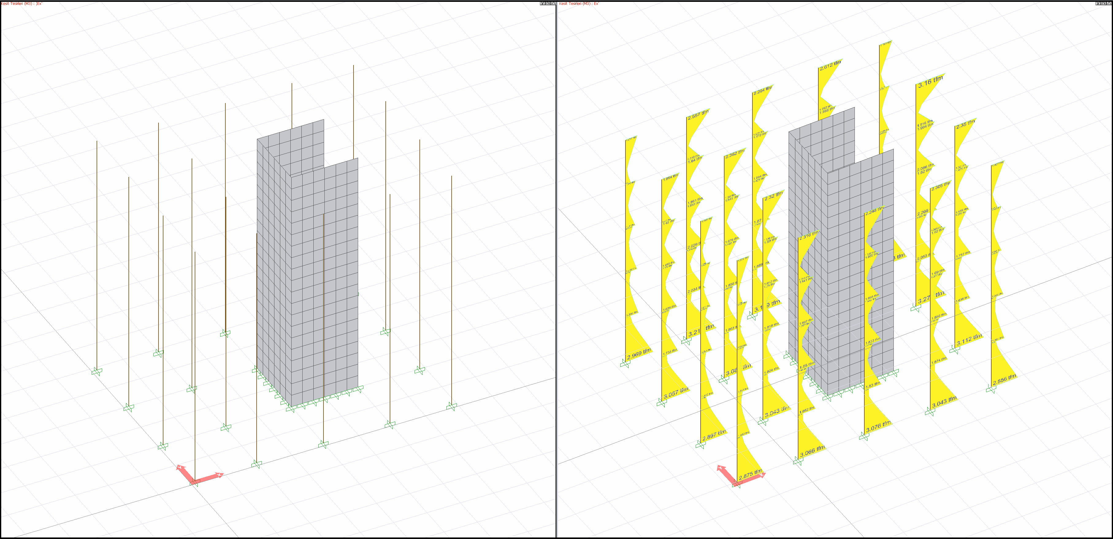
In the picture below , moment values occurring in the columns as a result of the earthquake calculation with the modal combination method of a building with no beams are shown. The calculation on the left side of the image is the results obtained as a result of the first stage calculation (both ends of the columns are articulated). As can be seen, there is no moment value because the two ends of the columns are hinged. The calculation on the right is the results of the second stage calculation. As you can see, as the columns are connected monolithically, moments occur at the column ends.
All elements are designed according to the most unfavorable case of internal forces occurring under all the loading combinations described above.