-
For walls meeting the H w / l w > 2.0 condition, the bending moments based on the design are taken as a constant value along the critical wall height determined according to 7.6.2.2 , equal to the bending moment calculated at the base of the wall according to Section 4 , the condition is automatically controlled.
-
Above the section where the critical wall height ends , the linear moment diagram parallel to the line combining the moments calculated at the base and top of the wall according to Section 4 is automatically applied.
-
In buildings with basements that meet the conditions given in 3.3.1.1 , the constant curtain moment is taken into account along the critical wall height defined in 7.6.2.2 .
-
The condition that design bending moments in all sections of walls with H w / l w ≤ 2.0 are equal to the bending moments calculated according to Section 4 is automatically applied.
-
In the case of H w / l w > 2.0, it is automatically checked whether the moment of bearing power of the wall sections at each floor is fulfilled for the columns in the strong direction of the wall , given by Equation (7.3) .
ICONS
H w = Total curtain height measured from the top of the foundation or the ground floor slab
H cr = Critical curtain height
l w = Length of the curtain or tie-beam curtain piece in plan
Polygon Curtain Design Bending Moments under H w / l w > 2 and H w / l w <= 2
Polygon curtain elements are modeled with shell finite elements. In this case, the stresses of the curtain element in each loading combination are calculated. The results of the polygon shear finite elements are defined in the center of gravity of the polygon shear section so as to provide the three-dimensional rigid body motion condition, and the values obtained from the shear finite element results of the relevant loading combination are collected at this center of gravity, and the internal forces of the polygon shear are obtained.
First , minimum longitudinal reinforcement and transverse reinforcement of polygonal curtain elements are determined in accordance with Section 7.6 of TBDY . The element strengths obtained with these reinforcements are compared with the design forces obtained from the calculation. If the strength values are smaller than the design forces, the required element strength is obtained by revising the stipulated reinforcements.
All loading conditions create stresses in the finite elements of the polygon wall. When these finite element results are gathered in the center of gravity of the polygon wall so as to provide three dimensional rigid body motion, the polygon wall creates a bending moment around both axes together with the axial load. In this case, a flexural strength is calculated for each normal force level in the two axes (strong and weak axes) of the polygon wall. All these strengths PM 2 M 3When moved to a graph in the form of the curtain 3-dimensional interaction curve is obtained. Flexural strength of walls is calculated by moment-curvature analysis since there will be different normal strength levels for each loading combination. The moment strength calculated at each normal force level forms the 3-dimensional interaction curve of the polygon curtain. While moment curvature analysis is performed in the entire polygon wall, a section cell (fiber or fiber) model is used, with the longitudinal reinforcements in the head regions and other regions in their positions.
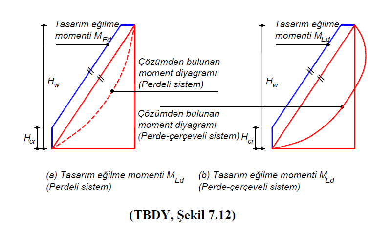
Design bending moments of polygonal walls with H w / l w > 2 according to TBDY clause 7.6.6.1 TBDY Figure 7.12 (a) and TBDY A constant value along the critical wall height, H cr , shown in Figure 7.12 (b) . Above the section where the wall height ends, the polygon is the values of the moment diagram parallel to the line combining the moments calculated at the base and top of the curtain. In walls meeting the H w / l w > 2 condition, bending moments, linear elastic deformations are expected along the critical height of the curtain, H cr . Therefore H cr is designed as a constant value equal to the base moment of the curtain across.
TBDY Article 7.6.6.1 according H w / l w > 2 condition design bending moment in the polygon screen which enables the TBDY Article 7.6.2.2 according to the polygonal wall base as a constant value over a defined critical wall height Chapter 4 'e bending calculated It is taken equal to the moment. The base moment of the polygon wall is the bending moment value calculated under the combined effect of vertical loads and earthquake loads. This bending moment continues steadily along the critical pitch height, H cr .
TBDY Figure 7.12 (a) and TBDY Figure 7.12 (b) "Moment diagram from the solution" represents the moment diagram for both systems (pitched, curtain-frame) under the combined effect of gravity loads and earthquake loads. The graph (blue color) shown with "design bending moment M Ed " is the moment diagram of the same value as the moment at the base of the wall along the critical curtain height, H cr . Critical pitch height, H crAt the upper part of the value is the moment diagram parallel to the line connecting the base moment of the curtain and the ceiling moment. This moment diagram is the moment diagram that will be used in the bending design of the polygon wall. After drawing the design bending moment diagram along the wall height, it is checked whether the design bending moment value is greater than the bending strength in each polygon wall section. In this calculation, biaxial moment interaction is taken into consideration together with the normal force.
Since the design bending moment graph in polygon walls depends on the base moment, it is made separately for all combinations. In other words, the design bending moment value is calculated separately for all combinations in walls. The Design Bending Moment diagram of polygonal walls is calculated for both axes (strong and weak axes). Since the curtain cross-sections are I, T, L, U, C or different in shape, both directions must be taken into account in the bending behavior. For this reason, the design bending moment value in polygon walls is calculated for both axes (strong and weak axes) for all combinations. Next, a 3D interaction curve (onion curve) is drawn where a bending strength is calculated for each normal force level. After these values, the design rates of the curtain are found for each combination.
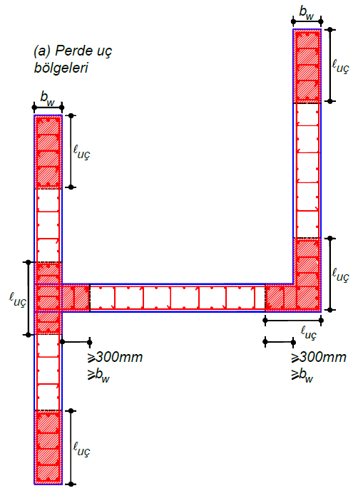
An example of a polygon curtain is shown in the picture below.