
In linear or non-linear performance analysis, the vertical loads acting on the building are evaluated by combining them with earthquake effects. Fixed vertical loads are the live load effect multiplied by the constant load effect and the live load participation coefficient. Performance analysis loading cases are handled under earthquake load effects, which are handled separately in both directions, together with vertical loads.
-
The combined effects of vertical loads and earthquake loads acting on the building are automatically calculated.
-
In the earthquake calculation, masses are automatically defined according to 4.5.9 .
-
Live Load Mass Participation Coefficient is determined by the user.
-
By using the live load participation coefficient, n, the nonlinear static calculation that takes the second order effects incrementally applied to the carrier system into account is applied automatically. The internal forces and deformations obtained from this calculation are automatically taken into account in the initial condition of the repulsion analysis.
-
Considering the vertical earthquake effect is under user control.
ICONS
E d (H) = Earthquake effect with direction coupling applied
E d (X) = Earthquake effect in the direction of (X)
E d (Y) = Earthquake effect in the direction of (Y)
E d (Z) = Vertical earthquake effect
G = Constant load effect
Q = Live load effect
Q e = Effective Live load effect
S = Snow load effect
g = Gravitational acceleration [m / s 2 ]
m j (S) = Singular mass acting on typical finite element node j [t]
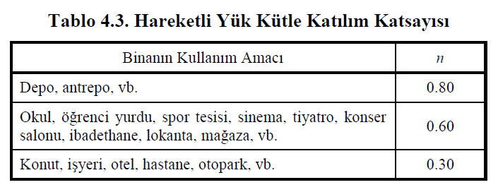
n = Live load contribution coefficient
w j (S) = Singular weight acting on typical finite element node j [kN]
w G, j (S) = Typical singular constant (under constant load effect) weight acting on finite element node j [kN]
w Q, j (S) = singular additional (under live load effect) weight acting on typical finite element node j [kN]
Earthquake performance of existing buildings is evaluated under the combined effects of vertical loads and earthquake effects on the building. In earthquake calculation, masses are defined according to TBDY Section 4.5.9 .
In the earthquake performance calculation of existing buildings, masses are defined at the joints of finite elements in accordance with Section 4.5.9 of TBDY . Where the joint point (rod or shell) of a typical finite element is j, the constant load, G and live load, mass due to the effect of Q at j point are calculated by Equation (4.16) . Live load mass participation coefficient, n, is a coefficient specified in Table 4.3 of TBDY and determined according to the building use purpose.

For j point of any finite element; w G, j (S) represents the constant load (G) at the node of the finite element and w Q, j (S ) represents the live load (Q) at the node of the finite element. In this case, the singular mass m j (S) value acting on the j node of the finite element is found by the relation w j (S) / g. Where g represents the acceleration of gravity.
As explained in Article 5.2.2.1 of TBDY , combining earthquake effect with vertical load effect is made with the following equation.

This equation shows G constant load effect, Q e effective live load effect, S snow load effect, E d (Z) vertical earthquake effect, E d (H) horizontal earthquake effect.
The effective live load effect Q e is calculated using the Live Load Mass Participation Coefficient, n, defined in Table 4.3 TBDY . It is calculated as Q e = nQ, where Q is the live load effect .
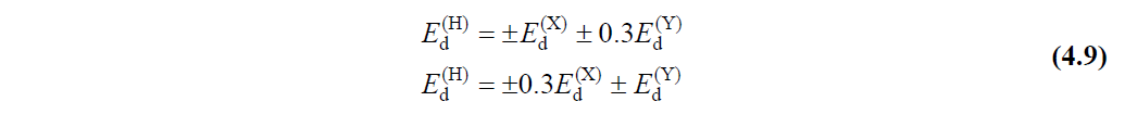
E d (H) represents the horizontal earthquake effect. If a performance evaluation is made in an existing structure with the Assessment and Design Based on Shape Change (ŞGDT) approach, the horizontal earthquake effect should be defined as in Article 5.2.2.3 of TBDY . If any of the pushing methods given in Section 5.6 of TBDY are applied to the system , the earthquake effects in the E d (H) , (X) and (Y) directions are calculated separately and then combined according to TBDY Section 4.4.2.1 . The earthquake effects defined in horizontal (X) and (Y) directions perpendicular to each other according to Section 4.4.2.1 of TBDY are combined as described in Equation (4.9) .
In this case, 8 different impulse calculations emerge when the push analysis is made for any structure. If the secondary earthquake direction and the effect of vertical loads are used and when performing the performance evaluation of an existing house (n = 0.3) structure without snow load, the earthquake combinations applied are as follows.
G + 0.3Q + E d (X) + 0.3E d (Y) + 0.3E d (Z) G + 0.3Q + E d (Y) + 0.3E d (X) + 0.3E d (Z)
G + 0.3Q + E d (X) -0.3E d (Y) + 0.3E d (Z) G + 0.3Q + E d (Y) -0.3E d (X) + 0.3E d (Z)
G + 0.3QE d (X) + 0.3E d (Y) + 0.3E d (Z) G + 0.3QE d (Y) + 0.3E d (X) + 0.3E d (Z)
G + 0.3QE d (X) -0.3E d (Y) + 0.3E d (Z) G + 0.3QE d (Y) -0.3E d (X) + 0.3E d (Z)
If the second earthquake direction is used but there is no vertical load effect and no snow load, the earthquake combinations applied when performing the performance evaluation of the building (n = 0.3) are as follows.
G+0.3Q+Ed(X)+0.3Ed(Y) G+0.3Q+Ed(Y)+0.3Ed(X)
G+0.3Q+Ed(X)-0.3Ed(Y) G+0.3Q+Ed(Y)-0.3Ed(X)
G+0.3Q-Ed(X)+0.3Ed(Y) G+0.3Q-Ed(Y)+0.3Ed(X)
G+0.3Q-Ed(X)-0.3Ed(Y) G+0.3Q-Ed(Y)-0.3Ed(X)
Similarly, the earthquake combinations applied when evaluating the performance of the existing house (n = 0.3) structure without secondary earthquake direction, vertical load effect and snow load are as follows.
G+0.3Q+Ed(X) G+0.3Q+Ed(Y)
G+0.3Q-Ed(X) G+0.3Q-Ed(Y)
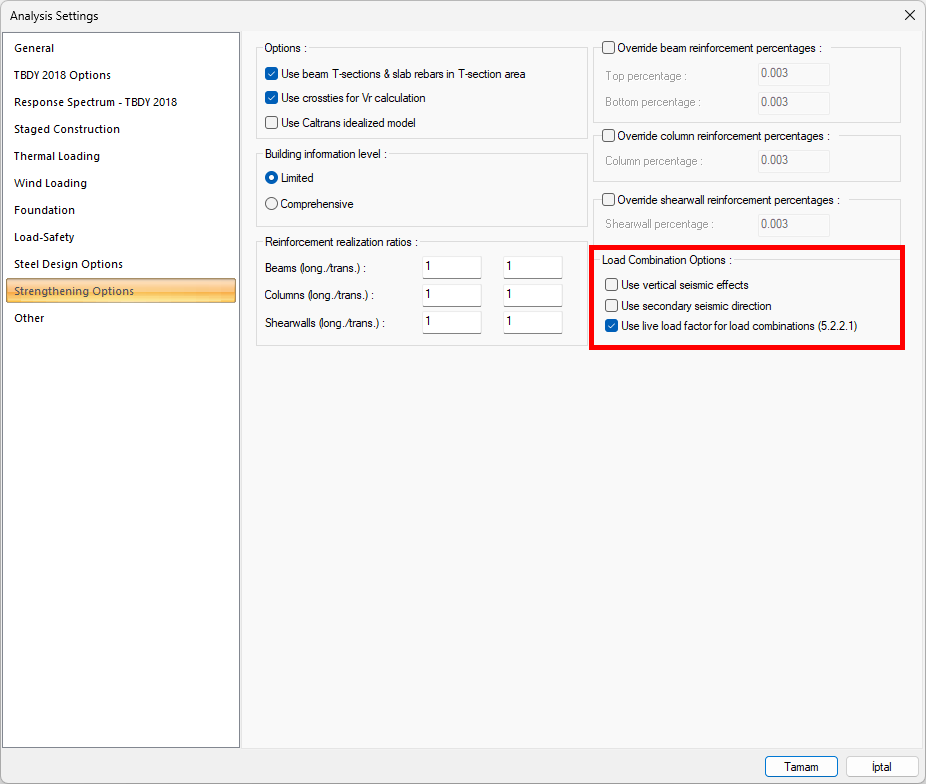
In the ŞGDT approach made within the scope of evaluation of existing structures, earthquake performance can be determined separately for all of the options described above. When any of the options shown below is selected, that loading state is automatically taken into account and performance evaluation is made.
Next Topic
Related Topics