
The angle dimension command displays the angle between two entities. It is used in plan and 2D drawing windows.
Location of the Angle Dimension Command
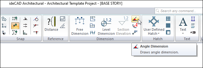
In the Architectural Program
You can access it under the Ribbon menu Drawings tab, Dimension heading.
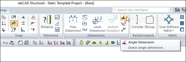
In Structural Program
You can access it under the Ribbon menu Drawings tab, Dimension heading.
Dimension Toolbar
|
Icons |
|---|
|
Outer dimension Outer dimension command runs. |
|
Inner dimension Inner dimension command runs. |
|
Free dimension Free dimension command runs. |
|
Intersection dimension Intersection dimension command runs. |
|
Label Runs the label command. The dimension label is drawn. |
|
Level dimension Draws level dimension in the plan window. |
|
Section elevation It is used for section elevation in section and view windows. Only active in 2D drawing windows. |
|
Angle dimension Dimensions the angle between two objects. |
|
Radius dimension Dimensions entities drawn with a circle or arc and arc or circle axis in diameter or radius. |
|
Section dimension group Creates a section dimension group. It is active in section and view windows. |
|
Section dimension Creates a section dimension. It is active in section and view windows. |
|
Include beams Include beams in dimension. |
|
Include slabs Include slabs in section dimension. |
|
Include details Include door/window elements in section dimension. |
|
Left side Places the section dimension on the left. |
|
Right side Places the section dimension on the right. |
|
Settings When clicked, which dimension type is active (inner, outer, intersection etc.) opens the dimension settings dialog where the parameters related to that dimension are found. |
Usage Steps
-
Click the Angle Dimension icon in the ribbon menu .
-
Two objects that intersect or can intersect are required.
-
Click the 1st and 2nd object respectively.
-
The shape of the cursor will revert to the shape of the angular measure. Decide the position of the angle by dragging the mouse.
-
Finish the dimensioning process by clicking the left button.
|
Usage step |
|---|
|
Selecting the 1st object to be dimensioned 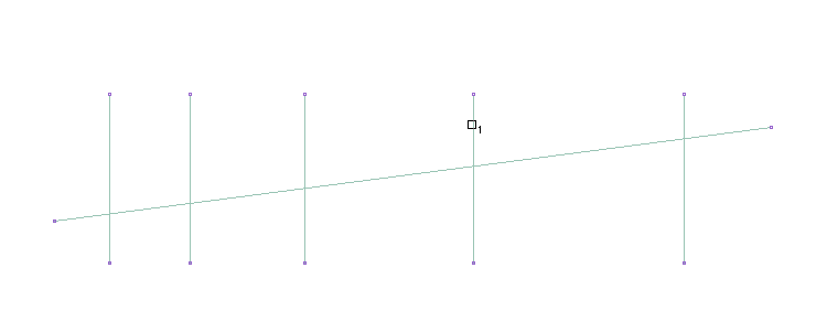
|
|
Selecting the 2nd object to be dimensioned 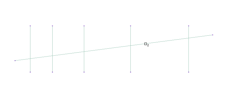
|
|
Creating an angle dimension preview 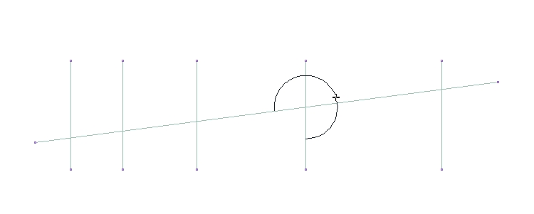
|
|
Positioning the angle dimension according to the movement of the mouse 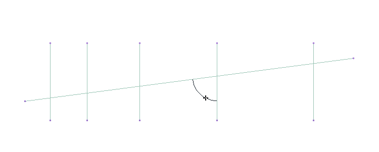
|
|
Angle dimension 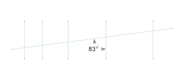
|
Location of Angle Dimension Settings Dialog
Angle Dimension Command Settings
You can access it under Level Dimension in the Drawings tab of the ribbon menu.
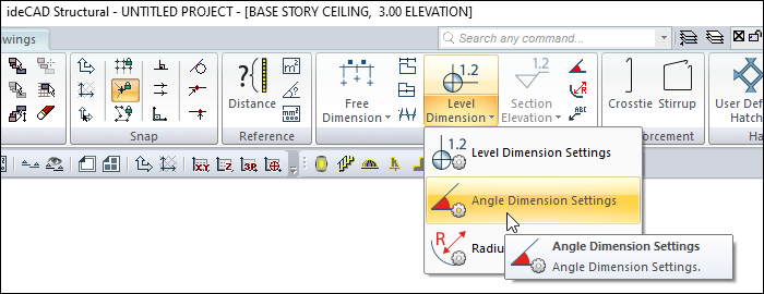
After running the angle dimension command, you can access it by clicking the Settings icon in the dimensioning assistant toolbar that appears on the screen.
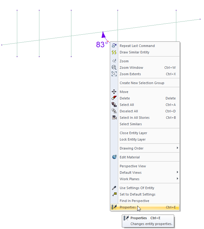
Angle Dimension Object Settings
Select the outer dimension that you want to enter its settings and click the Properties row from the menu that opens by clicking the right button of the mouse.
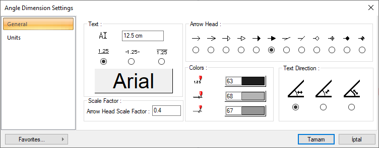
Angle Dimension Settings - General Tab
|
Specifications |
|---|
|
Text Section |
|
The font height of the dimensions is entered. |
|
The position of the dimension text relative to the dimension line is selected. |
|
When the button is clicked, the "Font Settings" dialog appears. Font of information text can be set here. |
|
Arrow head scale factor The factor determining the size of the dimension arrow is given. |
|
Arrow head 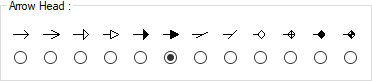
One of the 12 display types given for the angle dimension arrow is selected. |
|
Colors Section |
|
Sets the color of the dimension text. When the color box is clicked, the appropriate color is selected from the window that opens. |
|
Sets the color of the dimension lines. When the color box is clicked, the appropriate color is selected from the window that opens. |
|
Sets the color of the dimension arrows. When the color box is clicked, the appropriate color is selected from the window that opens. |
|
Text direction 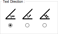
The position of the dimension text is set. |
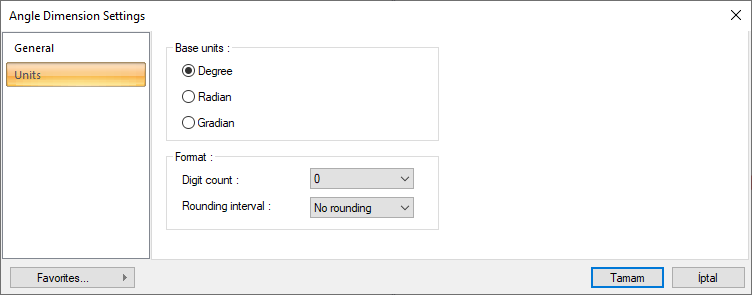
Angle Dimension Settings - Units Tab
|
Specifications |
|---|
|
Base units 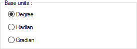
One of the selections is activated by clicking the left mouse button on the job. Degree : If marked, the unit of knowledge writing will be degrees.
|
|
Digit count 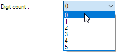
It determines how many digits will be shown after the comma. The wanted number is selected from the list. For example, if 2 is selected, units will be shown as two digits after the comma. If 0 is selected, units will not be shown after the comma. |
|
Rounding interval 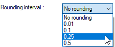
Determines the rounding range of the dimension to be made in degrees, radians or grad. If no rounding is selected, the dimensioning is done at exact value. As the range gets larger, the dimensioning is rounded up to the selected range. |
Next Topic